MTS SWIFT 20 Ultra Sensor User Manual
Page 89
Test Track Vehicle for Slip Ring Sensor
SWIFT 20 Sensors
Installing the Transducer
89
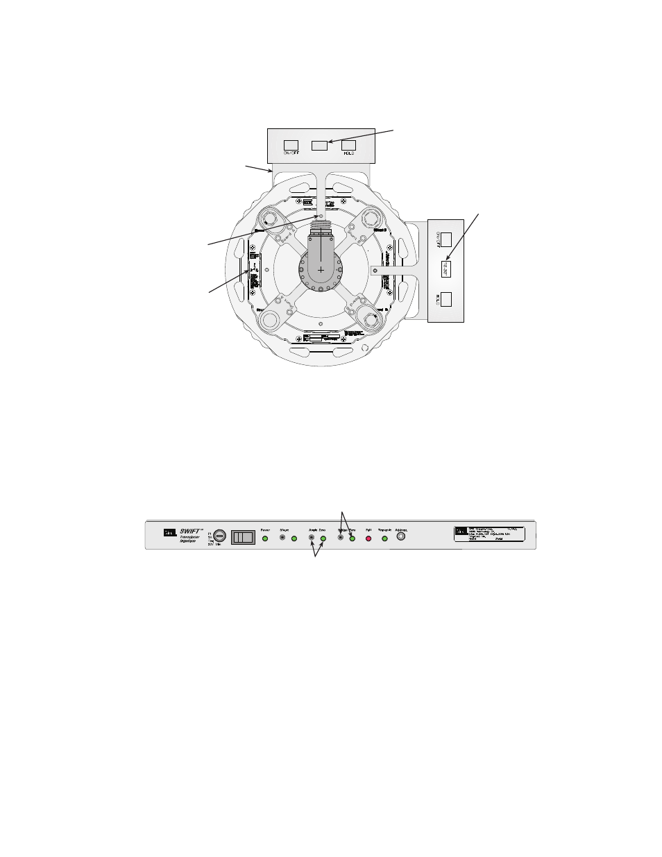
Note
If the anti-rotate assembly interferes with the mounting of the digital
inclinometer, use the alternate mounting location shown.
D.
Place the digital inclinometer on the bracket and rotate the tire until the
inclinometer reads 0.0°, ±0.1° (or 90.0°, ±0.1° if the alternate position
is used).
E.
Push the Bridge Zero button on the front of the TI box. The LED will
turn on for a few seconds, then start blinking rapidly. The Angle Zero
indicator will start blinking slowly.
F.
Remove the digital inclinometer and level bracket.
G.
Rotate the tire 90° in either direction.
H.
Attach the level bracket so that it again sits on top of the transducer.
Insert the locking pin through the bracket and into the pin pilot hole on
the transducer.
Digital Inclinometer
in this position
should read 0°, ±0.1°
Insert Lock Pin
in Pilot Hole
Level Bracket
S20-20
0.00°
Axes Icon
Digital Inclinometer
(alternate location)
in this position
should read 90°, ±0.1°
S20-21
Angle Zero
Switch and Indicator
Bridge Zero
Switch and Indicator
- Series 111 Accumulator (40 pages)
- Series 249G2 Swivels (34 pages)
- Series 201 Actuators (40 pages)
- Series 215 Rotary Actuator (68 pages)
- Series 242 Actuators (40 pages)
- Series 244 Actuators (68 pages)
- Series 247 Actuators (40 pages)
- Series 248 Actuators (46 pages)
- 709 Alignment System (158 pages)
- Series 609 Alignment Fixture (70 pages)
- 494 Controller Hardware FT 40 (344 pages)
- ReNew Technical Reference (50 pages)
- DCPD Measurement System (46 pages)
- Bionix EnviroBath (40 pages)
- FGW900 High-temperature Furnace (38 pages)
- Model 409.83 Temperature Controller (40 pages)
- Series 651 Environmental Chambers (30 pages)
- Series 653 High-Temperature Furnaces (38 pages)
- Series 658 Environmental Chamber (24 pages)
- Series FEC Environmental Chamber (48 pages)
- Model 685.53 Grip Control Module (24 pages)
- Series 685 Hydraulic Grip Supply (48 pages)
- Bend Fixture-10 kN (2 pages)
- Grip-Manual Bend Fixture-100 kN (2 pages)
- Grip-Manual Bollard-2 kN (2 pages)
- Grip-Manual Bollard-500 N (2 pages)
- Compression Platen-100 kN-100mm (2 pages)
- Compression Platen-100 kN-150mm (2 pages)
- Compression Platen-100 kN-200mm (2 pages)
- Compression Platen-20 kN (2 pages)
- Compression Platen-20 kN-100mm (2 pages)
- Compression Platen-20 kN-200mm (2 pages)
- Compression Platen-20 kN-SST (2 pages)
- Compression Platen-500 N FYC502A (2 pages)
- Compression Platen-500 N FYB502A (2 pages)
- Compression Platen-500 N-50mm (2 pages)
- Grip-Pneumatic Vise-Style-1 kN (2 pages)
- Pneumatic Bollard-500 N (2 pages)
- Scissor-Style-2 kN (2 pages)
- Scissor-Style-5 kN (2 pages)
- Screw-Style-5 kN (2 pages)
- Screw-Style-5 kN-SST (2 pages)
- Bend Fixture-1000 kN (2 pages)
- Bend Fixture-300 kN (2 pages)
- Bolt Grips (32 pages)