MTS SWIFT 20 Ultra Sensor User Manual
Page 20
SWIFT 20 Sensors
20
Construction
Hardware Overview
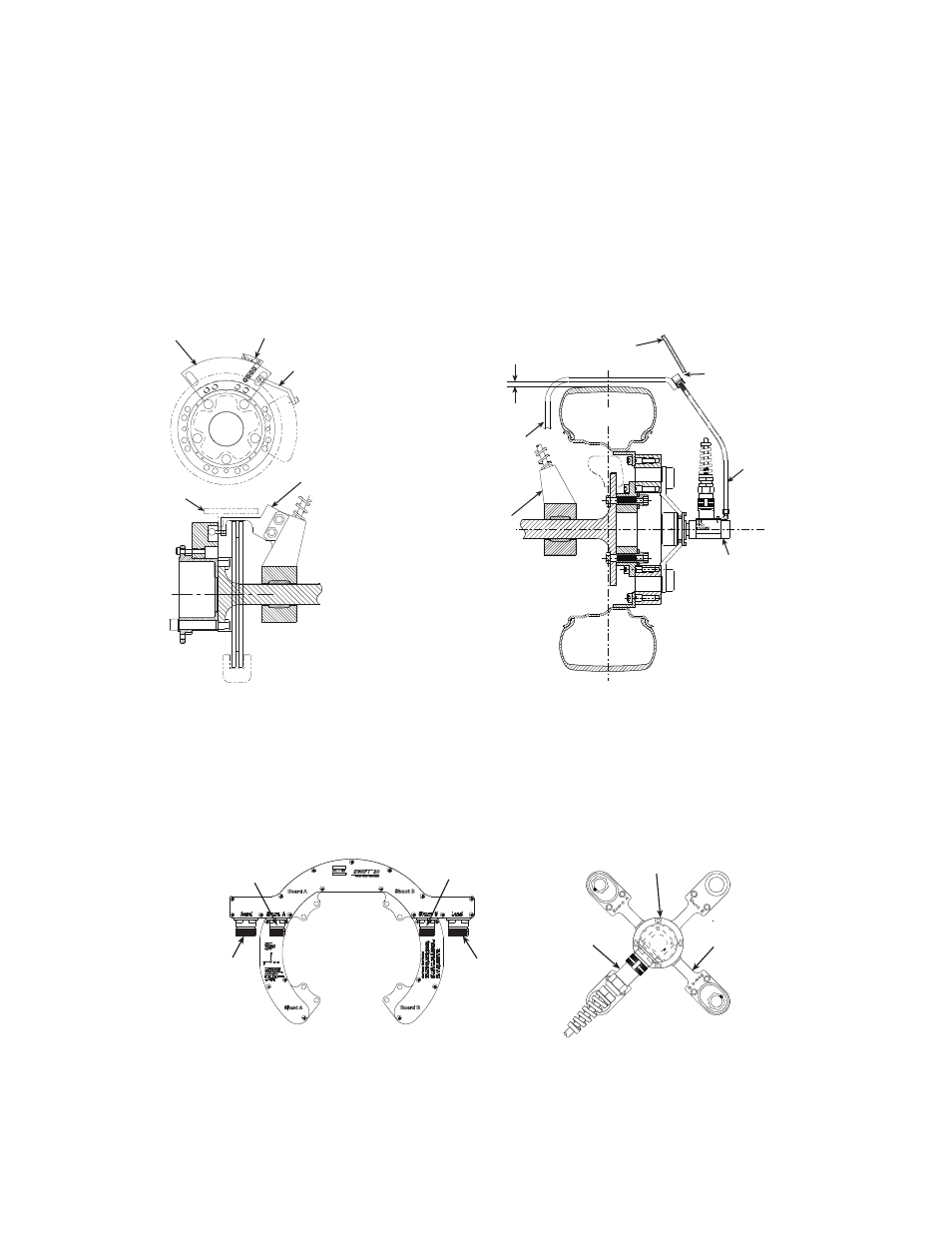
The slip ring anti-rotate device should be configured such that no loading occurs
to the slip ring throughout all loading and suspension travel. This means that
when you attach the anti-rotate device to the vehicle, you must consider all
possible motion of the suspension. The anti-rotate device should not bump
against the wheel well at any time; any jarring of the anti-rotate arm will damage
the slip ring. For steering axles, the anti-rotate bracket must be mounted to part of
the unsprung suspension that steers with the tire, such as the brake caliper. For
additional anti-rotate device mounting recommendations, refer to the Anti-Rotate
Customer/User Assembly drawing at the back of this manual.
Non-spinning
connector housing or
connector bracket
The non-spinning connector housing or the non-spinning connector bracket (both
shown below) provide a connection between the SWIFT and the TI electronics
for non-spinning use. Both assemblies incorporate rugged connectors suitable for
durability testing. The non-spinning connector housing can also include an
optional connector with built-in, tri-axial accelerometers.
S20-55
Slip Ring
Assembly
Suspension/
Unsprung Mass
Tire must not
hit bracket when
loaded or rotating.
Anti-Rotate Bracket
must be stiff
(preferably steel
or stiff aluminum
tubing).
Center line
of Wheel
Anti-Rotate
Assembly
Vehicle
Fender
Bracket must not
hit fender at
extreme end of
suspension travel
Slip Ring Model
Slip Ring Model
Cable Conduit
Bracket
Alignment Fixture
Example of
Anti-Rotate
Bracket Attached
to Brake Caliper
Example of
Anti-Rotate
Bracket Attached
to Strut
Cable
Conduit
Bracket
Telemetry Model
Accelerometer
(optional)
Shunt A
Load
Shunt B
S20-54
Connector Housing
S20-58
Non-Spinning
Cable Assembly
Non-Spinning
Connector Bracket
Spinning
Slip Ring
Bracket
Non-Spinning
Connector Bracket