2 master frequency input (dfin), Master frequency input (dfin), Configuration – Lenze EVF9333−xV User Manual
Page 267
Configuration
Function blocks
Master frequency input (DFIN)
8.2
8.2.2
l
8.2−5
EDSVF9333V EN 6.2−04/2012
8.2.2
Master frequency input (DFIN)
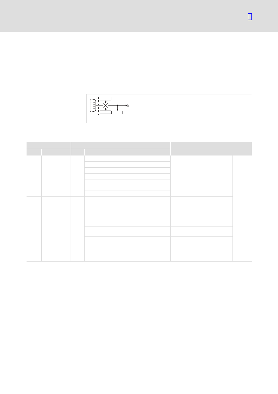
The function block calculates a speed signal from the rectangular signals at
X9. TTL signals and HTL signals can be connected. The zero track can be
selected as an option.
The edge changes are detected every 1 ms and result directly in the output
value.
C0425
C0427
DFIN
DFIN-OUT
C0426
X9
fb_dfin
Fig. 8.2−2
Digital frequency input (DFIN)
Codes for parameter setting
Code
Possible settings
IMPORTANT
No.
Name
Lenze Selection
C0425 DFIN const
3
0
256 inc/rev
Constant of the master frequency
input, function block DFIN
l
Output signal at the connected
encoder or at the upstream
controller in the event of a
master frequency
cascade/master frequency bus
^
8.2−5
1
512 inc/rev
2
1024 inc/rev
3
2048 inc/rev
4
4096 inc/rev
5
8192 inc/rev
6
16384 inc/rev
C0426 DIS: OUT
−36000
{1 rpm}
36000 Output signal of the master
frequency input, function block
DFIN
l
Display only
C0427 DFIN function
0
Function of the master frequency
input, function block DFIN
0
2−phase
l
Phase−displaced signal
sequence
1
A pulse/B dir
l
Control of direction of rotation
via track B
2
Pulse A or B
l
Control of speed and direction
of rotation via track A or track
B
Description