Commissioning, Stop – Lenze EVF9333−xV User Manual
Page 196
Commissioning
Adjusting the motor
Motor temperature monitoring with PTC or thermal contact
6.6
6.6.3
l
6.6−8
EDSVF9333V EN 6.2−04/2012
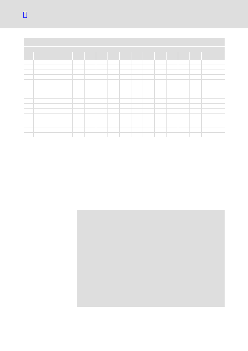
Motor data
Information on the motor
nameplate
C0076
C0075
C0071
C0070
C0091
C0090
C0089
C0088
C0087
C0085
C0084
C0081
C0022
C0086
Field
T
ni
V
pi
T
nn
V
pn
cos
j
U
r
[V]
f
r
[Hz]
IN
[A]
n
N
[rpm]
L
s
[mH]
R
s
[
W]
P
r
[kW]
Imax
[A]
Type
C86
1089
MDEBAXM−080−12
252
4.16
0.95
20.69
89.00
2510
2.77
87
400
0.68
6
300
1.6
2
1090
MDEBAXM−080−32
213
3.00
0.75
11.69
65.20
1400
2.00
50
400
0.72
6
300
3.5
2
1091
MDEBAXM−080−32
253
5.20
1.30
11.69
65.20
2510
3.46
87
400
0.72
6
300
1.9
3
1092
MDEBAXM−090−12
214
4.05
1.10
6.40
37.00
1420
2.70
50
400
0.77
6
300
2.5
2
1093
MDEBAXM−090−12
254
7.05
2.00
6.40
37.00
2535
4.70
87
400
0.77
6
300
2
2
1094
MDEBAXM−090−32
215
5.40
1.50
4.80
26.00
1415
3.60
50
400
0.77
6
300
2
2
1095
MDEBAXM−090−32
255
9.30
2.70
4.80
26.00
2530
6.20
87
400
0.77
6
300
1
2
1096
MDEBAXM−100−12
216
7.20
2.20
2.90
20.00
1425
4.80
50
400
0.80
6
300
1
1.5
1097
MDEBAXM−100−12
256
12.45
3.90
2.90
20.00
2535
8.30
87
400
0.80
6
300
0.8
1.5
1098
MDEBAXM−100−32
217
9.90
3.00
2.10
17.00
1415
6.60
50
400
0.81
6
300
2.5
1.5
1099
MDEBAXM−100−32
257
17.10
5.35
2.10
17.00
2530
11.40
87
400
0.81
6
300
1.4
1.8
1100
MDEBAXM−112−22
218
12.45
4.00
1.50
11.00
1435
8.30
50
400
0.82
6
300
2
2
1101
MDEBAXM−112−22
258
21.45
7.10
1.50
11.00
2545
14.30
87
400
0.82
6
300
1
2
1102
MDEBAXM−112−32
219
17.85
5.50
2.71
21.40
1425
11.90
50
400
0.84
6
300
1.5
10
1114
MDFMAxx−200−32
224
83.25
30.00
˘
˘
1465
55.50
50
400
0.85
6
300
1
2
1115
MDFMAxx−200−32
264
145.50
52.00
˘
˘
2575
97.00
87
400
0.85
6
300
1
2
6.6.3
Motor temperature monitoring with PTC or thermal contact
PTC resistors according to DIN 44081 and DIN 44082 can be connected via
the terminal inputs T1 and T2. The motor temperature is measured and
integrated into the drive monitoring.
A thermal contact (NC contact) can also be connected to T1 and T2. Lenze
three−phase AC motors provide thermal contacts as default.
When using motors equipped with PTC resistors or thermostats, we
recommend to always activate the PTC input. This prevents the motor from
being destroyed by overheating.
(
Stop!
ƒ
The motor temperature monitoring may only be connected to
T1, T2 if the cable is terminated with a PTC or thermal contact
(NC contact) on the motor side.
– An "open" cable acts like an antenna and can cause faults on
the drive controller.
– Input signals at T1, T2 are processed with a delay of 2 s.
ƒ
The drive controller can only evaluate one PTC resistor! Do not
connect several PTC resistors in series or in parallel:
– The motor temperature would be measured incorrectly.
– The motors could be destroyed by overheating.
ƒ
If you operate several motors on a drive controller, use
thermal contacts (NC contacts) for motor temperature
monitoring and connect these in series.
ƒ
To achieve full motor protection, an additional temperature
monitoring with separate evaluation must be installed.
Description