Status word (6041 – Lenze 2130IB User Manual
Page 64
L
62
4.2.4.
Status word (6041
hex
)
Data format:
Unsigned16
The parameter "status word" is used to show compact information about the
controller. It contains status information about controller states (page 56) and
further important information.
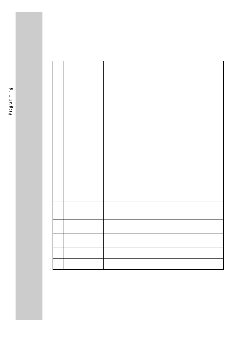
Structure of the parameter "status word"":
Bit
Name
Meaning
0
Ready to switch on
Controller status information
0 = State at least "READY TO SWITCH ON"
1 = State less than "READY TO SWITCH ON"
1
Switched on
Controller status information
0 = State at least "SWITCHED ON"
1 = State less than "SWITCHED ON"
2
Operation enable
Controller status information
0 = State at least "OPERATION ENABLE"
1 = State less than "OPERATION ENABLE"
3
Malfunction
Controller status information
0 = no malfunction (TRIP)
1 = malfunction (TRIP)
4
Voltage disabled
Information about command "Disable voltage" (see "control word").
0 = Command is active
1 = Command is not active
5
Quick stop
Information about command "Quick stop" (see "control word").
0 = Command is active
1 = Command is not active
6
Switch-on disabled
Controller status information
0 = Status not "SWITCH ON DISABLED"
1 = Status "SWITCH ON DISABLED"
7
Warning
Collective warning message
(Not supported by the base controllers at the moment)
0 = No warning
1 = Warning
8
Message
Collective message
(Not supported by the base controllers at the moment)
0 = No message
1 = Message
9
Remote
Bus access authority, depending on the Lenze parameter "operating
mode" (L-C001)
0 = L-C001 <> 5
1 = L-C001 = 5
10
Face value reached
State of speed/frequency deviation
0 = n
set
<>
n
actual
1 = n
set
=
n
actual
11
Limit value
State of speed/frequency limit
0 = Limit not activated
1 = Limit activated
12
reserved
DRIVECOM reserved
13
reserved
DRIVECOM reserved
14
free 1
For 4900/8600 mapping on the third freely assignable output
15
free 2
For 4900/8600 mapping on the fourth freely assignable output
The precise information about the present controller state can only be
obtained by the combination of the controller state information bit
(bit 0, 1, 2, 3, 4, 5, 6). This is shown in the following.