Lenze 2130IB User Manual
Page 20
L
18
How to wire the module
• Only use cables according to the following cable specification.
• Observe the following illustrations concerning the bus connector.
• Make the connection to the controllers using the bus connector.
The bus system is not interrupted if you disconnect the plug from
the controller.
• Connect a terminating resistor at the physical bus ends . This
resistor is integrated in the bus connection plug. You can activate it
by using a switch.
• If the 2130IB bus interface module is not supplied with power any
more, the bus system continues to operate. The connected
controller, however, cannot be called by the host.
• If you want to disconnect individual bus participants, make sure that
the terminating resistors at the physical cable ends remain active.
• Further notes and wiring instructions can be obtained from the
documentation of the control manufacturer.
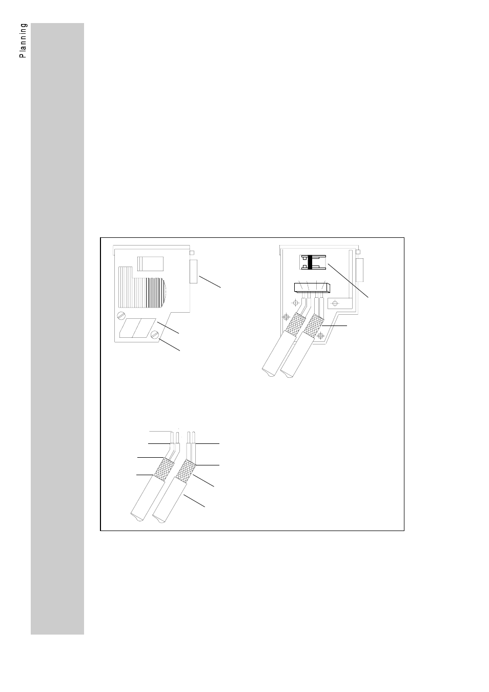
Connection of the bus cable in the bus connector
ON
A B A B
4
5
V
V
1 = 9-pole SubD connector
2 = Guides for the bus cable
3 = Housing screw
4 = Terminating resistor (not connected))
5 = Cable screen; must lay bare
on the metal guide
V
1
2
3
V
V
approx. 6 mm
approx. 11 mm
approx. 11 mm
cable screen
bus cable
V
V