Dakota Ultrasonics DFX-8 plus MANUAL2 User Manual
Page 42
38
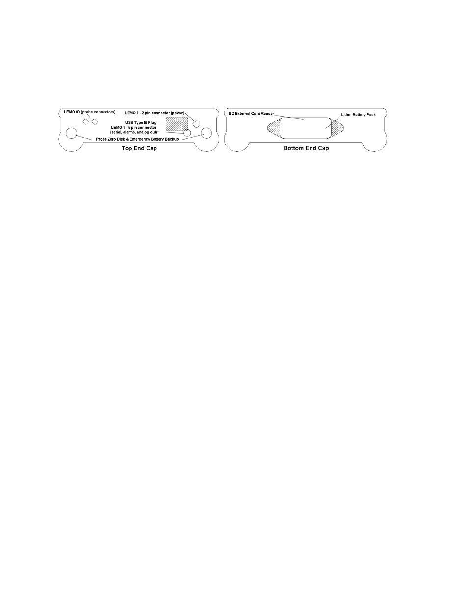
3.26 Top & Bottom End Caps
The top & bottom end panels are where all connections are made to the DFX-8. The
diagram above shows the layout and description of the connectors:
Transducer Connectors
Refer to Diagram: The transducer connectors, emergency battery backup
channels/probe zero disks, power connector and auxiliary connector are located on
the DFX-8’s top end cap. The transducer connectors are of type Lemo “00”. Note:
There is no polarity associated with connecting the transducer to the DFX-8.
Probe Zero Disk & Battery Cover
Refer to Diagram: The emergency battery backup disks are the large round disks
shown in the diagram. Note: This same disk is also used as a probe zero disk.
Simply remove the cover when replacing the batteries (3 AA cells) for each. When
performing a manual probe zero function, simply place the transducer on disk making
firm contact. Important: Be sure to follow the polarity label located on the back label
of the DFX-8. Note: Rechargeable batteries can be used, however they must be
recharged outside of the unit in a standalone battery charger.
USB Type B Connector
Refer to Diagram: The USB connector is a common type B connector found on a
variety of electronic devices. This port will be used to transfer stored grid/log files,
captured screen shots, etc. This connector will also be used to upgrade the DFX-8
with the latest version of firmware (gauge software). The cable supplied with the
DFX-8
is USB type A to USB type B.
RS-232 Serial Connection (LEMO 1 – 5 pin)
Refer to Diagram: The RS-232 connector is a 5 pin female Lemo 1 connector. It is
designed to connect directly from the DFX-8 to a standard AT serial port on a PC,
and will be used in conjunction with our proprietary java application software called
“Remote Commander”. The primary purpose of the Remote Commander software,
will be for use in conjunction with a projector connected to a PC for classroom
training programs and demonstration purposes. An accessory 9 pin female serial to
Lemo 1 - 5 pin male cable will be required to use this feature, and is not included in
the standard kit.