5 s/pdif transmitter, 5 s/pdif transmitter -11, Table 7-9. s/pdif transmitter pins -11 – Cirrus Logic CS4953xx User Manual
Page 77
7-11
Copyright 2010 Cirrus Logic, Inc.
DS732UM10
Digital Audio Output Port Description
CS4953xx Hardware User’s Manual
shows values and messages for the output channel configuration parameter.
7.1.5 S/PDIF Transmitter
Two S/PDIF transmitters are provided on the XMTA and XMTB pins that can output an IEC60958-
compliant S/PDIF stream. The modulation clock source for the S/PDIF transmitter is the clock present on
the DAO_MCLK pin. The sample rate of the transmitter will be the same setting as for the respective DAO
port.
The DSP has an internal multiplexer that can be used to route an external S/PDIF signal from the
XMTA_IN or XMTB_IN pin directly to the respective XMTA/XMITB S/PDIF output pin instead of the
internally generated S/PDIF signal.
To summarize the XMTA/XMITB S/PDIF output pins can be configured as:
•
I
2
S output - Default
•
S/PDIF Transmitter - Sent config from
•
DSP Bypass - Send config from
The DSP Bypass config is typically used to route a S/PDIF stream from input to the output for recording
applications or as a PCM bypass for dual-zone applications. A soft reset is required when switching
between any of the above modes.
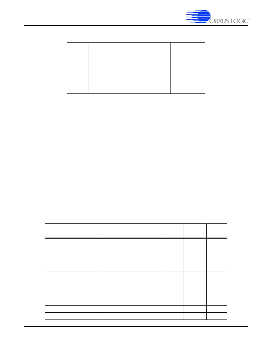
Table 7-8. Output Channel Configuration (Parameter G)
G Value
Channel Configuration
Hex Message
0
(default)
2 Channels
0x8180002C
0xFFFFF8FF
0x8140002C
0x00000700
1
6 Channels
0x8180002C
0xFFFFF8FF
0x8140002C
0x00000400
Table 7-9. S/PDIF Transmitter Pins
Pin Name
Pin Description
LQFP-
144 Pin #
LQFP-
128 Pin #
Pin
Type
XMTA_IN
S/PDIF Input for XMTA mux
The XMTA_IN S/PDIF inputs is
muxed with XMTA to allow
switching the S/PDIF output
between the internal and
external sources
2
-
Input
XMTB_IN
S/PDIF Input for XMTB mux
The XMTB_IN S/PDIF inputs is
muxed with XMTB to allow
switching the S/PDIF output
between the internal and
external sources
92
-
Input
DAO1_DATA3/
XMTA
S/PDIF Audio Output A
15
47
Output
DAO2_DATA3/
XMTB
S/PDIF Audio Output B
5
35
Output