3 i2c port, 1 i2c system bus description, C port – Cirrus Logic CS4953xx User Manual
Page 34: C system bus description
I2C Port
CS4953xx Hardware User’s Manual
DS732UM10
Copyright 2010 Cirrus Logic, Inc
3-2
3.3 I
2
C Port
The CS4953xx I
2
C bus has been developed for 8-bit digital control applications, such as those requiring
microcontrollers. The I
2
C bus interface is a bidirectional serial port that uses 2 lines (data and clock) for
data transmission and reception with software-addressable external devices. Each external device
interfaced to the CS4953xx I
2
C port has the ability to communicate directly with the other devices and is
assigned a unique address whether it is a CPU, memory, or some other device. A block diagram of the
CS4953xx I
2
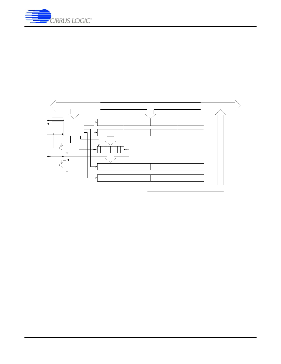
C Serial Control Port is provided in
Figure 3-1. Serial Control Port Internal Block Diagram
3.3.1 I
2
C System Bus Description
Devices can be considered masters or slaves when performing data transfers. A master is the device
which initiates a data transfer on the bus and generates the clock signals to permit that transfer. Any
device addressed by the initiator is considered a slave.
The CS4953xx has two serial ports. However, the O/S currently supports only slave mode host
communication on SCP1, and master mode communication on SCP2 for booting from a serial EEPROM/
FLASH.
The I
2
C-bus is a multi-master bus. This means that more than one device capable of controlling the bus
can be connected to it. The master-slave relationships found on the I
2
C bus are not permanent and only
depend on the direction of data transfer at that time. Generation of clock signals on the I
2
C bus is always
the responsibility of master devices; each master generates its own clock signals when transferring data
on the bus. Bus clock signals from a master can only be altered when they are stretched by a slow slave
device holding down SCP1_CLK.
Both SCP1_SDA and SCP1_CLK are bidirectional lines. When the bus is free, both lines are pulled high
by resistors. The output stages of devices connected to the bus must have an open-drain or open-
collector to perform the wired-AND function.
I2C Control /
Clocking
SCP1_BSY
SCP1_IRQ
LSB (Byte 0)
Byte 1
Byte2
MSB (Byte 3)
LSB (Byte 0)
Byte 1
Byte2
MSB (Byte 3)
MSB (Byte 3)
Byte 2
Byte1
LSB (Byte 0)
MSB (Byte 3)
Byte 2
Byte1
LSB (Byte 0)
7 6 5 4 3 2 1 0
Internal Bus
SCP1_SDA
SCP1_CLK
EN
EN