Table 9-8. reset pin -14, Table 9-9. hardware strap pins -14 – Cirrus Logic CS4953xx User Manual
Page 102
Control
CS4953xx Hardware User’s Manual
DS732UM10
Copyright 2010 Cirrus Logic, Inc
9-14
Configuration and control of the CS4953xx decoder and its peripherals are indirectly executed through a
messaging protocol supported by the operating system (O/S) running on the DSP. In other words,
successful communication can only be accomplished by following the low-level hardware communication
format and high-level messaging protocol. The specifications of the messaging protocol used by the O/S
can be found in AN288, “CS4953xx/Cs497xxx Firmware User’s Manual”
.
The system designer only needs
to read the subsection describing the communication mode being used. The CS4953xx Hardware User’s
Manual explains each communication mode in more detail.
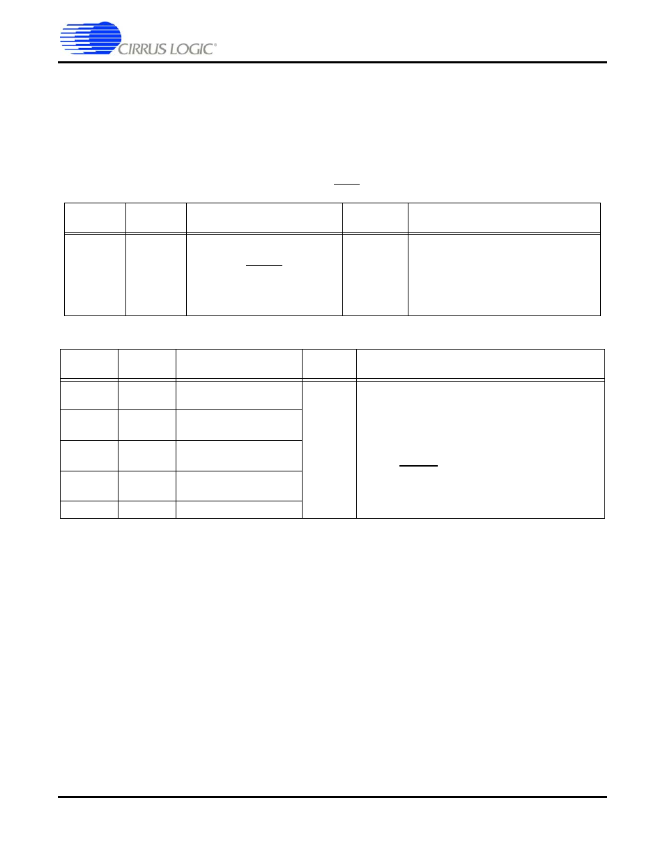
Table 9-8. Reset Pin
LQFP-144
Pin #
LQFP-128
Pin #
Pin Name
Pin Type
Pin Description
93
121
RESET
Input
Reset, async. active-low Chip Reset
Reset should be low at power-up to
initialize the DSP and to guarantee
that the device is not active during
initial power-on stabilization periods.
Table 9-9. Hardware Strap Pins
LQFP-144
Pin #
LQFP-128
Pin #
Pin Name
Pin Type
Pin Description
7
39
DAO2_DATA1, HS4,
GPIO19
Input
Operational Mode Select
Pull-up or Pull-down resistors on these pins set
the DSP operational mode at reset. Hardware
Strap Mode Select
The state of these pins is latched at the rising
edge of
RESET
. The boot ROM uses the state of
these pins to select the boot mode.
11
43
DAO2_DATA0, HS3,
GPIO18
16
48
DAO1_DATA2, HS2,
GPIO16
17
49
DAO1_DATA1, HS1,
GPIO15
19
51
DAO1_DATA0, HS0