Chapter 7: digital audio output interface, 1 digital audio output port description, 1 dao pin description – Cirrus Logic CS4953xx User Manual
Page 67: Chapter 7. digital audio output interface -1, 1 digital audio output port description -1, 1 dao pin description -1, Chapter 7 digital audio output interface
7-1
Copyright 2010 Cirrus Logic, Inc.
DS732UM10
Digital Audio Output Port Description
CS4953xx Hardware User’s Manual
Chapter 7
Digital Audio Output Interface
The CS4953xx has two output ports - Digital Audio Output port 1 & 2 (DAO1 & DAO2). Each port can
output 8 channels of up to 32-bit PCM data. The Digital Audio Output ports are both implemented with a
modified 3-wire Inter-IC Sound (I
2
S) interface along with an oversampling master clock (MCLK). The I
2
S
interface includes a frame clock at the current sampling frequency (LRCLK), a bit clock for clocking the
bits of the audio word (SCLK), and 4 audio data output signals (DATA[3:0]). Each of the output data
signals can be connected to the digital stereo input of an audio digital-to-analog converter (DAC) for up to
8 channels of stereo PCM output per DAO port for a total of 16 digital audio output channels.
Each DAO port may slave to an externally generated SCLK and LRCLK or it may master these clocks if
MCLK is provided. Each port can be configured as having an independent clock domain in slave mode, or
the ratio of the two clocks can be set to even multiples of each other in master mode. Additionally, the two
ports can be ganged together into a single clock domain. The port supports data rates from 32 kHz to
192 kHz. Each port can also be configured to provide a 32-kHz to 192-kHz S/PDIF transmitter (XMTA and
XMTB) as an output.
illustrates the DAO block diagram.
7.1 Digital Audio Output Port Description
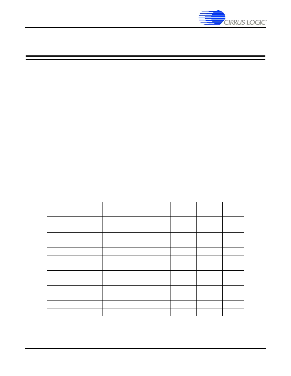
7.1.1 DAO Pin Description
identifies the pins associated with the Digital Audio Output Ports (DAO1 and DAO2).
DAO_MCLK is the master clock and is firmware configurable to be either an input (slave) or an output
(master). If MCLK is to be used as an output, the internal PLL must be used. As an output MCLK can be
configured to provide a 128Fs, 256Fs, or 512Fs clock, where Fs is the output sample rate.
Table 7-1. Digital Audio Output (DAO1 & DAO2) Pins
Pin Name
Pin Description
LQFP-144
Pin #
LQFP-128
Pin #
Pin
Type
DAO1_LRCLK
Sample Rate Clock
22
54
I/O
DAO1_SCLK
Bit Clock
20
52
I/O
DAO1_DATA0
Digital Audio Output
19
51
Output
DAO1_DATA1
Digital Audio Output
17
49
Output
DAO1_DATA2
Digital Audio Output
16
48
Output
DAO1_DATA3/XMTA
Digital Audio Output
15
47
Output
DAO2_LRCLK
Sample Rate Clock
14
46
I/O
DAO2_SCLK
Bit Clock
12
44
I/O
DAO2_DATA0
Digital Audio Output
11
43
Output
DAO2_DATA1
Digital Audio Output
7
39
Output
DAO2_DATA2
Digital Audio Output
6
38
Output
DAO2_DATA3/XMTB
Digital Audio Output
5
35
Output
DAO_MCLK
Master Clock
8
40
I/O