1 performing a serial spi write, 2 spi write protocol, Figure 3-15. spi write flow diagram -17 – Cirrus Logic CS4953xx User Manual
Page 49
3-17
Copyright 2010 Cirrus Logic, Inc.
DS732UM10
SPI Port
CS4953xx Hardware User’s Manual
3.4.3.1 Performing a Serial SPI Write
Information provided in this section is intended as a functional description indicating how to perform an
SPI write from an external device (master) to the CS4953xx DSP (slave). The system designer must
ensure that all timing constraints of the SPI Write Cycle are met (see the CS4953xx datasheet for timing
specifications). When performing an SPI write, the same protocol is used whether writing single-word
messages to the boot firmware, writing multiple-word overlay images to the boot firmware, or writing
multiple-word messages to the application firmware. The example shown in this section can be
generalized to fit any SPI write situation.
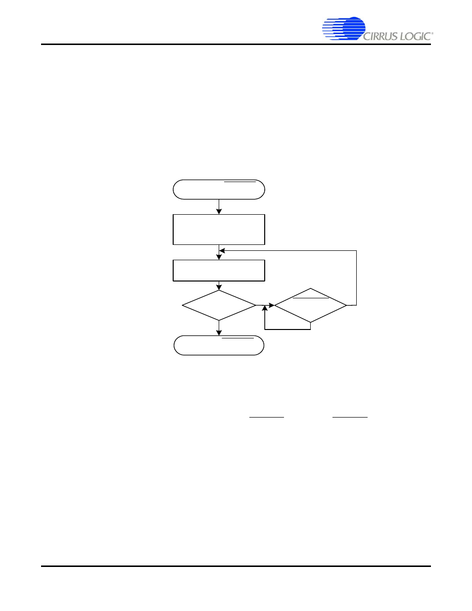
The flow diagram shown in
illustrates the sequence of events that define the SPI write
protocol.
describes the Serial SPI Write protocol.
Figure 3-15. SPI Write Flow Diagram
3.4.3.2 SPI Write Protocol
1.
An SPI transfer is initiated when the chip select SCP1_CS is driven low. SCP1_CS driven low
indicates that CS4953xx is in SPI slave mode.
2. This is followed by a 7-bit address and the read/write bit set low for a write. So, the master should
send 0x80. The 0x80 byte represents the 7-bit SPI address 1000000b, and the least significant bit set
to ‘0’, designates a write.
3. The master should then clock the 4-byte data word into the slave device, most-significant bit first, one
byte at a time. The data byte is transferred to the CS4953xx DSP (slave) on the falling edge of the
eighth serial clock. For this reason, the serial clock should be held low so that eight transitions from
low-to-high-to-low will occur for each byte.
4. If the master has no more data words to write to the CS4953xx, then proceed to Step 6. If the master
has more data words to write to the CS4953xx, then proceed to Step 5.
SPI START: SCP1_CS
(LOW)
WRITE ADDRESS BYTE
0x80
MORE DATA?
Y
N
WRITE 4 DATA BYTES
SPI STOP: SCP1_CS
(HIGH)
SCP1_BSY
(LOW)?
N
Y