Timing diagram, sto, 2 timing diagram, sto, Fig. 4.2 timing diagram, sto 2 – Festo Контроллер двигателя CMMD-AS User Manual
Page 81
4. Functional safety engineering
Festo P.BE-CMMD-AS-HW-EN 1002NH
81
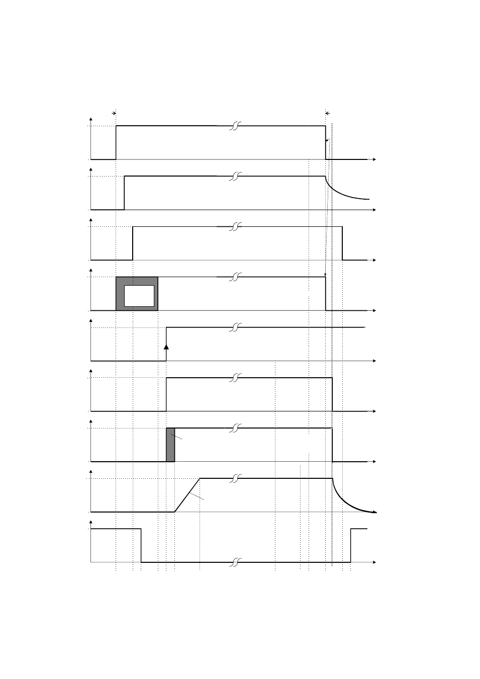
4.2.2
Timing diagram, STO
t1
t2 t3
t5 t6
t7
t8
t10
t11
t12 t13
t9
t4
t
t
t
t
t
t
t
t
t
Triggering of pulse amplifier supply relay (optocoupler driver)
Supply of pulse amplifiers (optocoupler driver)
“ON“ (15V)
“OFF”
open
closed
“ON”
Timing of output
stage enabling
variable
Internal output stage enabling
(controlled by µP)
Set speed "n"
n=0
n
“H”
“H”
“H”
Seven-segment
display
Delay until brake is
released!
2. shut-down path
1. shut-down path
Discharge curve of
electrolytic capacitors for the
supply of the pulse amplifiers
“OFF”
“ON”
“OFF”
Ramp can be set via
Festo Configuration Tool
„FCT“
fixed
(0V)
Can be set via
Festo Configuration Tool „FCT“
Releasing motor holding brake (X6.Y.1/2)
released
(24V)
Controller enabling (X1.Y, DIN5)
Output stage enabling (X1.Y, DIN4)
Floating feedback contact for driver supply
(X3.Y.5/6)
Timing for activation of "Safe
Torque off" with safety
switchgear PNOZ.
"Safe Torque off"
X3.Y.2 (0V)
X3.Y.2 (24V)
"Safe Torque off"
tx
tx
= 1.6 ms (controller cycle time)
Y
= 1 / 2, depending on the axis
14535d_1
Fig. 4.2 Timing diagram, STO
2