Interfaces and plug assignments, I/o interface [x1.1/2, 4 interfaces and plug assignments – Festo Контроллер двигателя CMMD-AS User Manual
Page 105: 1 i/o interface [x1.1/2
6. Electrical installation
Festo P.BE-CMMD-AS-HW-EN 1002NH
105
6.4
Interfaces and plug assignments
6.4.1
I/O interface [X1.1/2]
Mode switching allows assignment of the [X1] interface more than once.
As a result, a maximum of four different I/O assignments can be selected. These are
described in the following tables:
- Table 6.2 Pin allocation: I/O interface [X1] mode 0
- Table 6.3 Pin allocation: I/O interface [X1] mode 1
- Table 6.4 Pin allocation: I/O interface [X1] mode 2
- Table 6.5 Pin allocation: I/O interface [X1] mode 3
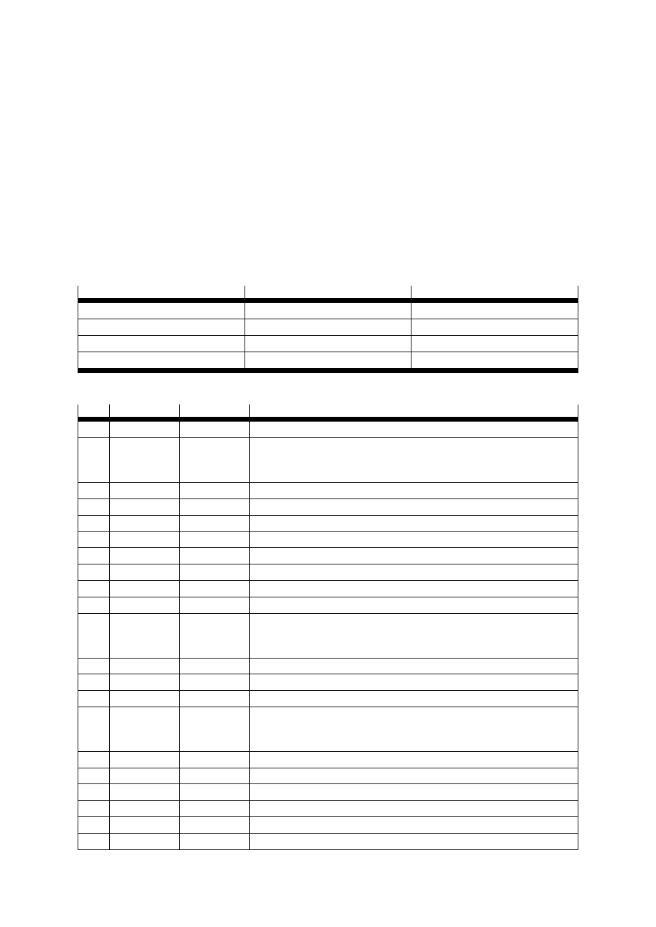
Mode
DIN9
DIN12
Mode 0 – Positioning
0
0
Mode 1 – Jog mode
0
1
Mode 2 – Route program
1
0
Mode 3 – Synchronisation
1
1
Table 6.1 Mode switching
Pin
Designation
Value
Mode = 0 – Positioning
1
AGND
0 V
Screen for analogue signals
2
AIN0 / DIN12 ±10 V
Digital I/O control interface: DIN12 Mode selection (high active)
Analogue input control interface:
Setpoint input 0, differential, maximum 30 V input voltage
3
DIN10
Record selection 4 (high active)
4
+VREF
+10 V ±4 %
Reference output for setpoint potentiometer
5
free
6
GND24
Ass.GND
Reference potential for digital inputs and outputs
7
DIN1
Record selection 1 (high active)
8
DIN3
Record selection 3 (high active)
9
DIN5
Controller release EN (high active)
10
DIN7
Limit switch 1
11
DIN9
Digital I/O control interface: Mode selection (high active)
Fieldbus contorl interface:
Sample input (high-speed input)
12
DOUT1
24 V100 mA
Output freely programmable – default: Motion complete (high active)
13
DOUT3
24 V100 mA
Output freely programmable – default: Error (low active)
14
AGND
0 V
Reference potential for the analogue signals
15
#AIN0 /
DIN13
Ri = 20 k
Digital I/O control interface: Stop input (low active)
Analogue input control interface:
Reference potential setpoint input 0, differential
16
DIN11
Record selection 5 (high active)
17
AMON0
0 ... 10 V
Analogue monitor output 0
18
+ 24 V
24 V100 mA
24 V feed-in feed-out
19
DIN0
Record selection 0 (high active)
20
DIN2
Record selection 2 (high active)
21
DIN4
Output stage enable (high active)