Timing diagram, operating mode shift, Setpoint value processing, 2 setpoint value processing – Festo Контроллер двигателя CMMD-AS User Manual
Page 50
3. Product description
50
Festo P.BE-CMMD-AS-HW-EN 1002NH
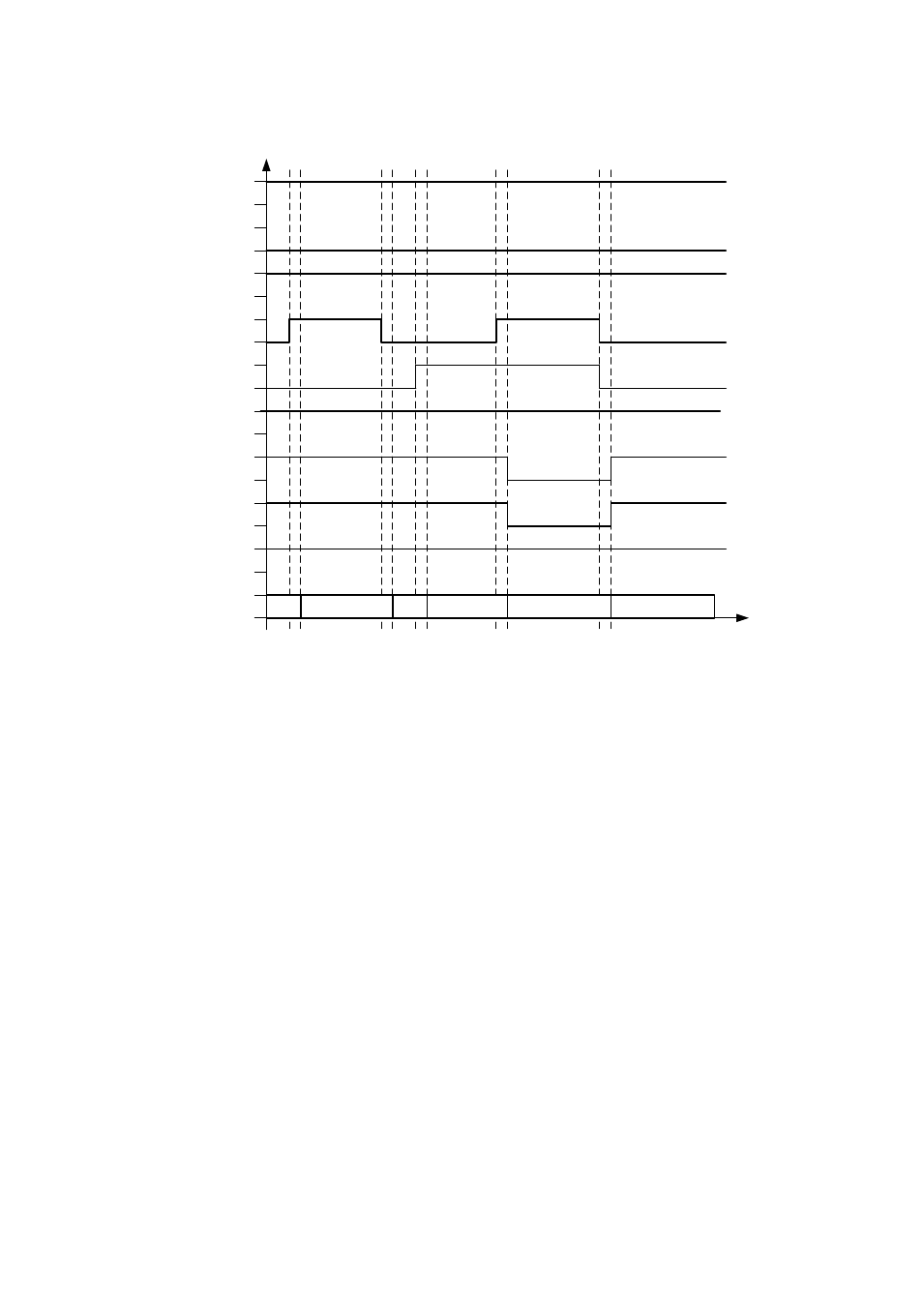
Timing diagram, operating mode shift
ENABLE
STOP
DIN12
1
0
1
0
1
0
1
0
0
1
0
1
0
1
0
1
0
DIN9
1
0
1
DOUT0: READY
DOUT1: MC
DOUT2: ACK
DOUT3: ERROR
2
1
1
3
4
1
t1
t1
t1
t1
t1
t1
= 1.6 ms
1)
Positioning
2)
Sequences / Route program
3)
Jog / Teach
4)
Synchronisation
Fig. 3.3 Timing for activation of the individual operating modes
3.7.2
Setpoint value processing
Setpoint value selectors allow you to switch setpoint values from various sources to the
corresponding controllers. The following setpoint value selectors are implemented in the
firmware:
- Selector for the speed setpoint
- Auxiliary value selector whose setpoint value is added to the speed setpoint.
The position of the setpoint value selectors is saved in non-volatile parameters.
Depending on the prefix, the speed setpoint is disabled via the signal of the
corresponding limit switch input. The limit switch inputs also affect the ramp generator for
the speed setpoint.
The speed setpoint (without the auxiliary setpoint) is reached via a setpoint ramp. It
permits setting various accelerations and brake decelerations in both directions so the
resulting setpoint value process can be adjusted to the path dynamics of motor and load.
The setpoint ramp can be deactivated.