Safe stop [x3.1/2, Field bus can [x4, Rs232/rs485 [x5 – Festo Контроллер двигателя CMMD-AS User Manual
Page 109: 3 safe stop [x3.1/2, 4 field bus can [x4
6. Electrical installation
Festo P.BE-CMMD-AS-HW-EN 1002NH
109
6.4.3
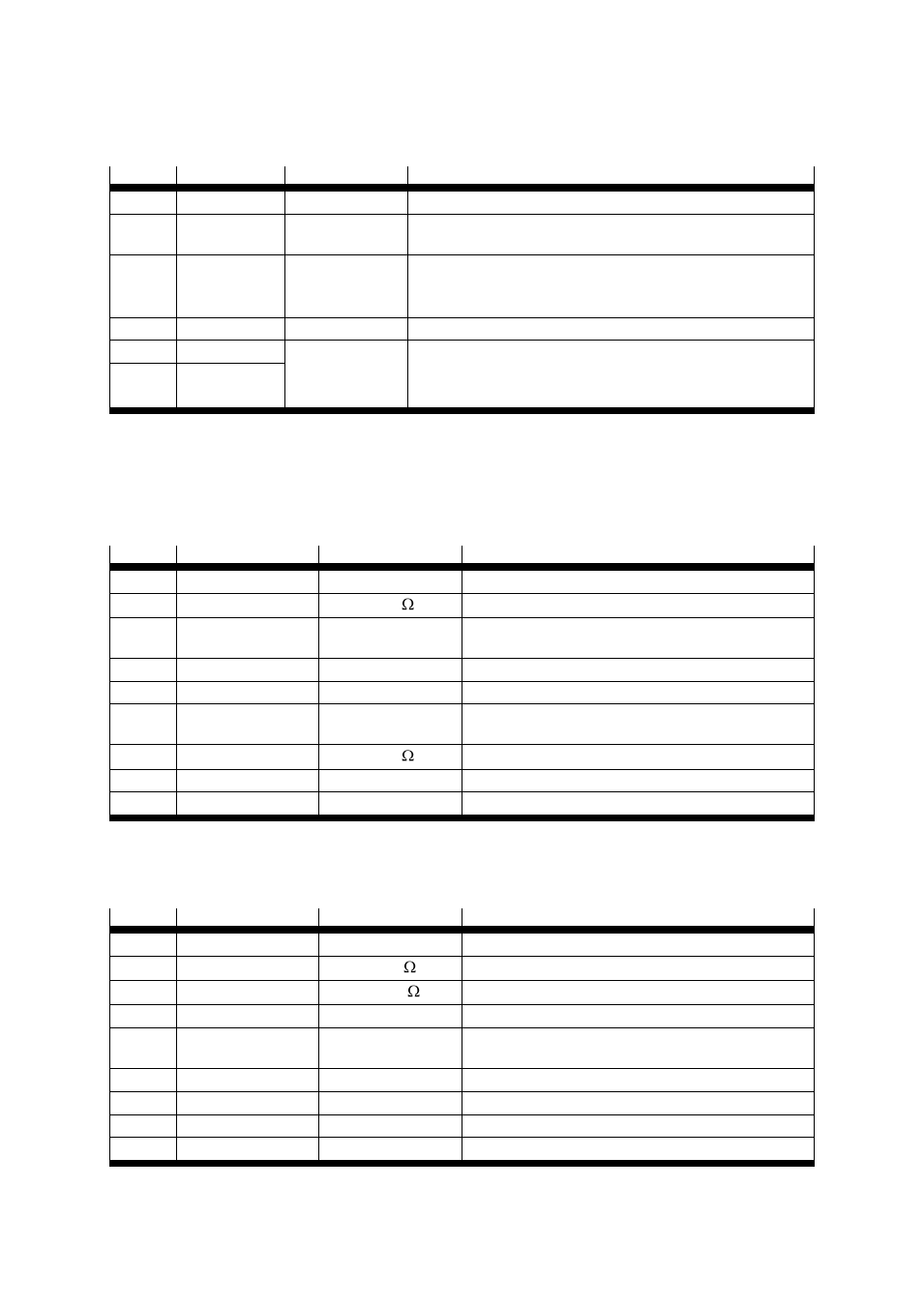
Safe stop [X3.1/2]
Pin no.
Designation
Value
Specification
1
24V
24 V DC
24 VDC supply carried out
2
REL
0 V/24 V DC
Setting and resetting the relay for interrupting the driver
supply
3
0V
0 V
[GND 24 V DC *)]
Reference potential for PLC
[Reference potential for the 24V DC power supply and for the
PLC *)]
4
UNASSIGNED
–
–
5
NC1
Max. 60 V AC
30 V DC
2 A
Potential-free feedback contact for driver supply,
normally closed contact.
6
NC2
* Reference potential for the 24V DC power supply and for the PLC
Table 6.7 Pin allocation "Safe halt" [X3.1/2]
6.4.4
Field bus CAN [X4]
Pin
Designation
Value
Specification
1
–
–
–
2
CANL
5 V, Ri = 60
CAN-low signal line
3
GND
0 V
CAN-GND, electrically connected to GND
in the controller
4
–
–
–
5
Screening
–
Connection for the cable screen
6
GND
0 V
CAN-GND, electrically connected to GND
in the controller
7
CANH
5 V, Ri = 60
CAN-high signal line
8
–
–
–
9
–
–
–
Table 6.8 Pin allocation: Field bus CAN [X4]
6.4.5
RS232/RS485 [X5]
Pin
Designation
Value
Specification
1
–
–
–
2
RS232_RxD
10 V, Ri > 2 k
Reception line
3
RS232_ TxD
10 V, Ra < 2 k
Transmission line
4
RS485_A
–
–
5
GND
0 V
RS232/485 GND, galvanically connected to GND in
the controller
6
–
–
–
7
–
–
–
8
+5 V_Fuse
5 V
Via PTC on plug
9
RS485_B
–
–
Table 6.9 Pin allocation: RS232/RS485 [X5]