Motor connection [x6.1/2, Power supply [x9, 6 motor connection [x6.1/2 – Festo Контроллер двигателя CMMD-AS User Manual
Page 110: 7 power supply [x9
6. Electrical installation
110
Festo P.BE-CMMD-AS-HW-EN 1002NH
6.4.6
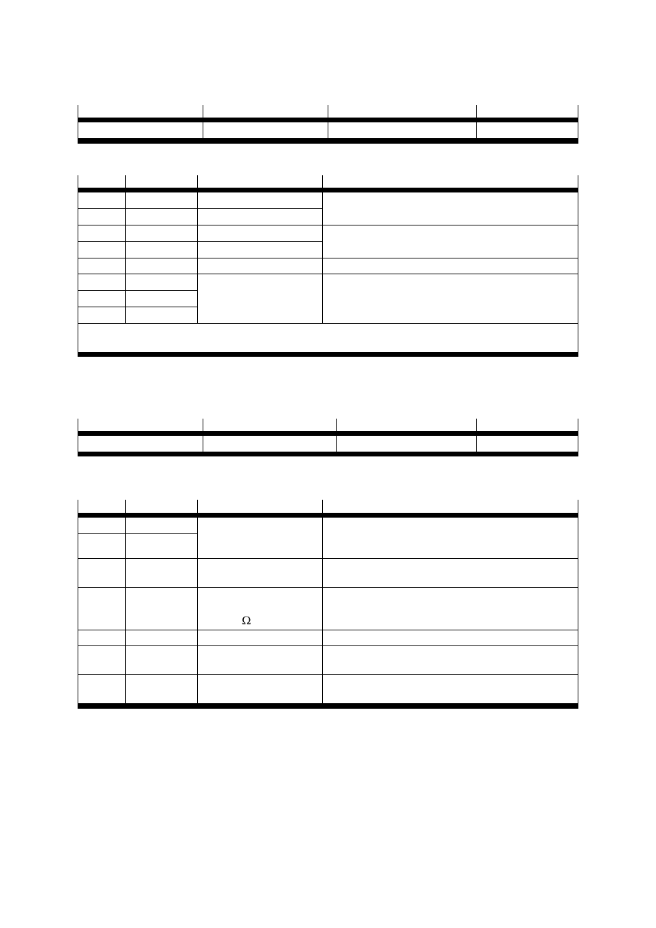
Motor connection [X6.1/2]:
Version on controller
Counterplug
Plugged/optional plug set
Material number
Combicon, 8-pin socket
MSTB 2.5/8-ST-5.08 BK
Blanking plug kit
547 452
Table 6.10 Plug version: Motor connection [X6]
Pin no.
Designation
Value
Specification
1
BR–
0 V brake
Motor holding brake,
signal level dependent on switch condition
2
BR+
24 V brake
3
–MTdig
0 V Temp.
Motor temperature sensor, NC, NO, PTC, KTY.
4
+MTdig
+3.3 V / 5 mA
5
PE
PE motor connection
PE connection in the motor cable
6
W
See technical
specifications
Connection of the 3 motor phases *
7
V
8
U
*The motor cable screen is fitted to the controller housing (The fastening flange is specially shaped for
this.)
Table 6.11 Pin allocation: Motor connection [X6]
6.4.7
Power supply [X9]
Version on controller
Counterplug
Plugged/optional plug set
Material number
Combicon, 7-pin socket
MSTB 2.5/7-G-ST-5.08 BK
Plugged
547 452
Table 6.12 Plug version: Power supply [X9]
Pin no.
Designation
Value
Specification
1
L1
Single-phase, 95 ... 255 V
AC, suitable for USA/EU
mains voltage
Mains voltage connection for ZK
2
N
3
ZK +
320 V DC
ZK+ connection for external brake resistance,
not short-circuit-proof against L1, N and PE!
4
BR-CH
0 V / 400 V,
max. 4 A
R
BR
> 100
Connection for external brake resistance against ZK+
5
PE
PE
PE connection of the mains power supply
6
24V
+24 V / 1 A
Supply for the control portion with DCDC converter,
DOUT0 to DOUT3 and holding brake, max. 1A
7
0V
GND
Common reference potential for the logic power
supply and the control section
Table 6.13 Pin allocation: Power supply [X9]