Festo Контроллер двигателя CMMD-AS User Manual
Page 107
6. Electrical installation
Festo P.BE-CMMD-AS-HW-EN 1002NH
107
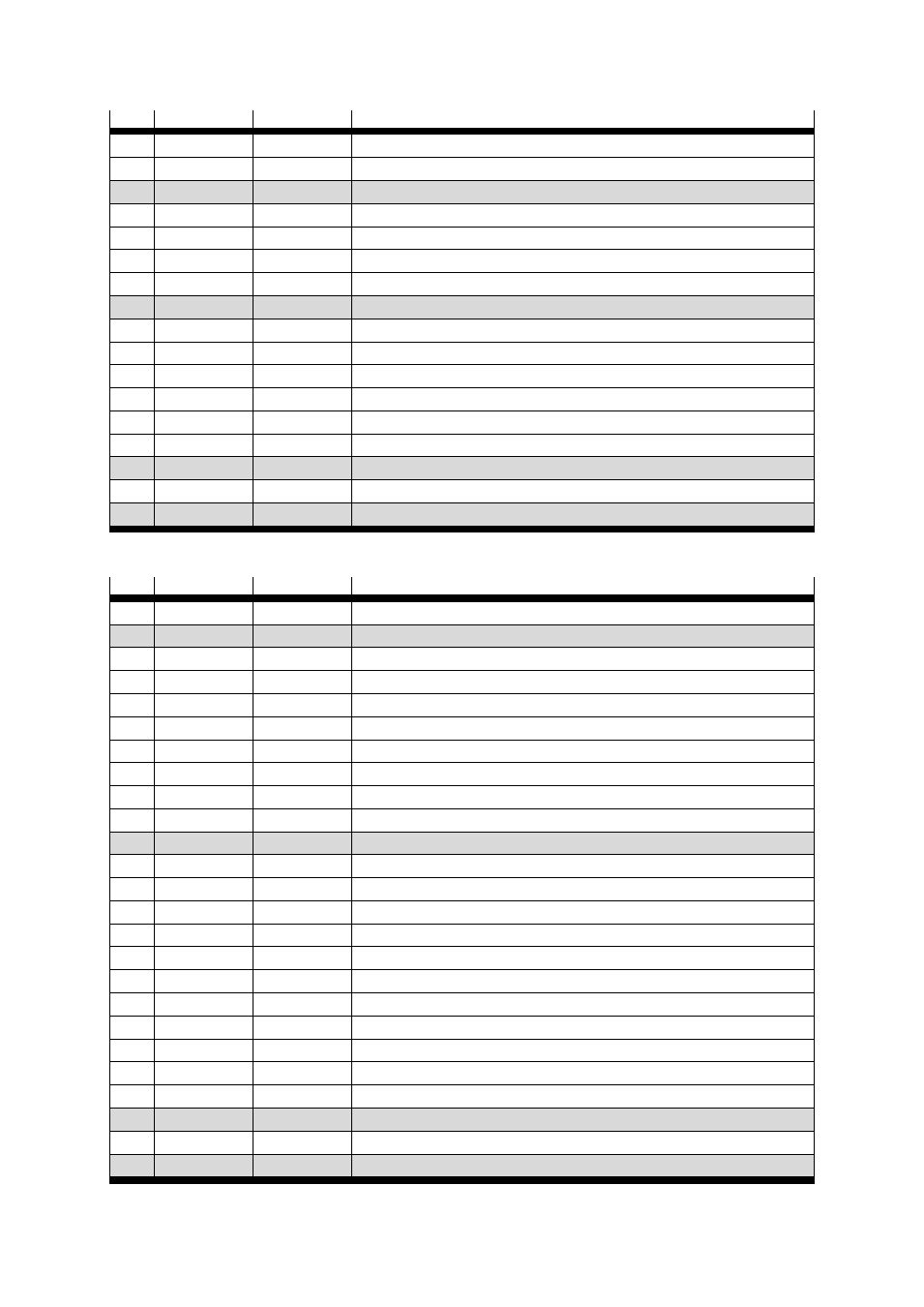
Pin
Designation
Value
Mode = 2 – Route program
9
DIN5
Controller release (high active)
10
DIN7
Limit switch 1
11
DIN9
Mode switch "1" = route program
12
DOUT1
24 V100 mA
Output freely programmable – default motion complete (high active)
13
DOUT3
24 V100 mA
Output freely programmable – default error (low active)
14
AGND
0 V
Reference potential for the analogue signals
15
DIN13
Stop input (low active)
16
DIN11
Next 2
17
AMON0
0 ... 10 V
Analogue monitor output 0
18
+ 24 V
24 V100 mA
24 V feed-in feed-out
19
DIN0
Record selection 0 (high active)
20
DIN2
Record selection 2 (high active)
21
DIN4
Output stage enable (high active)
22
DIN6
Limit switch 0
23
DIN8
Start route program
24
DOUT0
24 V100 mA
Ready for operation output (high active)
25
DOUT2
24 V100 mA
Output freely programmable – default start ack (high active)
Table 6.4 Pin allocation: I/O interface [X1] mode 2
Pin
Designation
Value
Mode = 3 – Synchronisation
1
AGND
0 V
Screen for analogue signals
2
DIN12
Mode switch slave synchronisation "1" = synchronisation
3
DIN10
4
+VREF
+10 V ±4 %
Reference output for setpoint potentiometer
5
Free
6
GND24
Reference potential for digital inputs and outputs
7
DIN1
Record selection 1 (high active)
8
DIN3
24 V
Direction_24 /CCW
9
DIN5
Controller release (high active)
10
DIN7
Limit switch 1
11
DIN9
Mode switch slave synchronisation "1" = synchronisation
12
DOUT1
24 V100 mA
Output freely programmable – default motion complete (high active)
13
DOUT3
24 V100 mA
Output freely programmable – default error (low active)
14
AGND
0 V
Reference potential for the analogue signals
15
DIN13
Stop input (low active)
16
DIN11
17
AMON0
0 ... 10 V
Analogue monitor output 0
18
+ 24 V
24 V100 mA
24 V feed-in feed-out
19
DIN0
Record selection 0 (high active)
20
DIN2
24 V
Pulse_24 / CW
21
DIN4
Output stage enable (high active)
22
DIN6
Limit switch 0
23
DIN8
Start synchronization
24
DOUT0
24 V100 mA
Ready for operation output (high active)
25
DOUT2
24 V100 mA
Setpoint output reached (high active)
Table 6.5 Pin allocation: I/O interface [X1] mode 3