Operation and display components, Status display, Control elements – Festo Контроллер двигателя CMMD-AS User Manual
Page 126: A.2.1, A.2.2, A.2 operation and display components, A.2.1 status display, A.2.2 control elements
A. Technical data
126
Festo P.BE-CMMD-AS-HW-EN 1002NH
A.2 Operation and display components
The CMMD-AS motor controller has two LEDs on the front and one
7-segment display for showing the operating status.
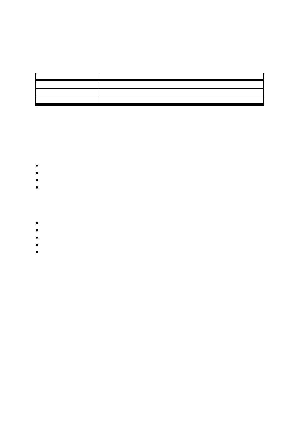
Element
Function
7-segment display
Displays the operating mode and an error code should an error occur
Ready LED (green)
Ready status
Bus LED (yellow)
CAN bus status display
Table A.5 Display elements
A.2.1
Status display
Ready
2 x LED green
CAN bus active
2 x LED yellow
Status display
2 x 7 segment display, blue
The following status information is shown on the 7-segment display (see chapter 8.2.1):
End stage enabled (bar)
Motor turning – speed control operating mode (segment rotation)
Positioning operation – display P with alternating record number
Error with number (flashing error number, three-position)
A.2.2
Control elements
The node number can be set via DIP switches on the front of the device:
7 x node number
1x Load firmware from SD card
2 x Baud rate
1 X CAN on / off
1 x Terminating resistor
The second axis gets the address of the first axis +1
Node number
Slave
= node number
Master
+1
Bus modules (PROFIBUS and DeviceNet) must be plugged into the extension slot [Ext1].
The bus modules are automatically recognised when the controller is switched on.
For PROFIBUS and DeviceNet, only the bus address specified on the DIP switches is
assigned; the data for two controllers are send in a shared telegram.