Allied Telesis AT-SBx81CFC960 User Manual
Page 236
Chapter 12: Replacing Modules
236
Section II: Installing the Chassis
Note
If the power wires are connected to the terminal block with the right
angle terminals, go to step 5.
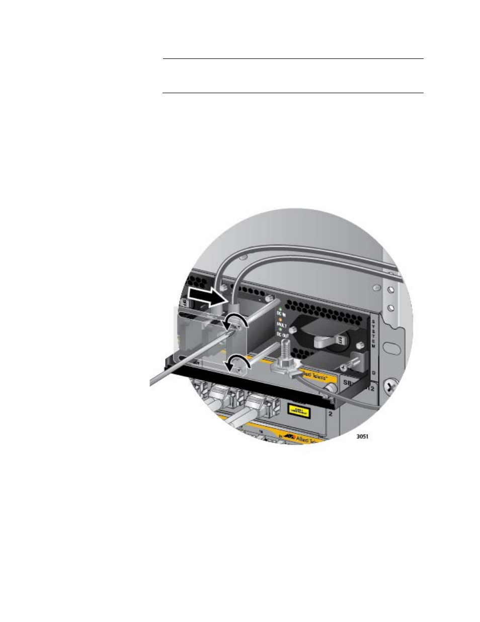
4. Use a #1 screwdriver to loosen the two screws that secure the plastic
cover over the terminal block and slide the cover to the right. You may
need to slightly lift the locking handle to access the bottom screw.
Refer to Figure 155.
The plastic cover may not be present if you used the right angle
terminals to connect the lead wires to the terminal block. If this is the
case, you may skip this step.
Figure 155. Opening the Plastic Window over the Terminal Block
5. Use a #3 screwdriver to remove the negative (-) lead wire from the
terminal block. The negative lead wire is on the right. Refer to Figure
156 on page 237.