Connecting bare dc power wires – Allied Telesis AT-SBx81CFC960 User Manual
Page 199
SwitchBlade x8112 Chassis Switch and AT-SBx81CFC960 Card Installation Guide
Section II: Installing the Chassis
199
Connecting Bare
DC Power Wires
To attach bare lead wires to the positive and negative terminals on the
power supply, perform the following procedure:
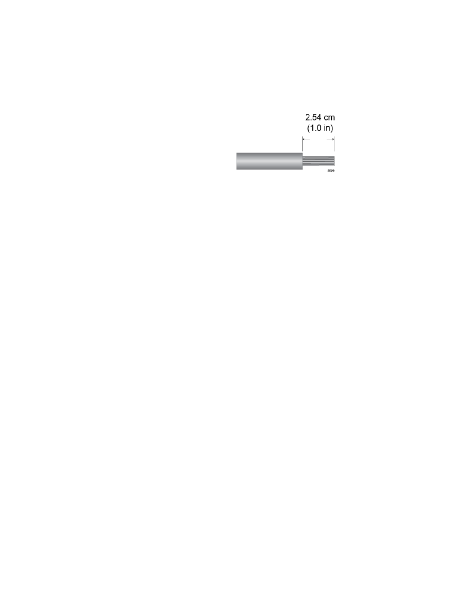
1. Prepare adequate lengths of two solid or stranded 8 AWG DC power
wires by stripping them as shown in Figure 141.
Figure 141. Stripping Solid or Stranded DC Power Wires
2. Use a #1 Phillips-head screwdriver to loosen the two screws on the
plastic cover over the positive and negative terminals on the power
supply and slide the cover to the right, as shown in Figure 128 on page
187. You may need to lift the locking handle slightly to access the
bottom screw.
3. Use a #3 Phillips-head screwdriver to remove the two screws from the
positive and negative terminals, as shown in Figure 129 on page 188.
4. Wrap the positive lead wire clockwise around one of the terminal
screws and secure the screw and wire to the positive terminal
connection on the terminal block with a #3 Phillips-head screwdriver.
The positive terminal is on the left.
You may attach the wire to the terminal so that it extends either above
or below the terminal block. Figure 142 on page 200 shows the wire
above the terminal block. Allied Telesis recommends tightening the
screw to 30 to 40 inch-lbs.