Allied Telesis AT-SBx81CFC960 User Manual
Page 116
Chapter 6: Installing the Power Supplies
116
Section II: Installing the Chassis
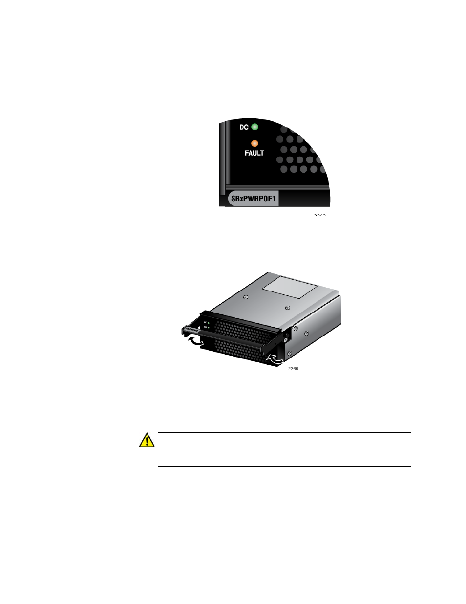
4. Check the model name, shown in Figure 53, to verify the module.
If the module is the AT-SBxPWRSYS1 System Power Supply, do not
continue with this procedure. Instead, perform “Installing the AT-
SBxPWRSYS1 AC System Power Supply” on page 107.
Figure 53. Verifying the AT-SBxPWRPOE1 PoE Power Supply
5. Raise the locking handle on the AT-SBxPWRPOE1 Power Supply, as
Figure 54. Unlocking the Handle on the AT-SBxPWRPOE1 Power Supply
6. Align and insert the AT-SBxPWRPOE1 Module into slot A or B. Figure
55 on page 117 shows the power supply module aligned in slot A.
Caution
The AT-SBxPWRPOE1 AC Power Supply will not work in slot C or
D.
This manual is related to the following products: