Unpacking the at-sbx8106 chassis, Figure 32: components of the at-sbx8106 chassis – Allied Telesis AT-SBx81CFC960 User Manual
Page 94
Chapter 5: Installing the Chassis in an Equipment Rack
94
Section II: Installing the Chassis
Unpacking the AT-SBx8106 Chassis
To unpack the AT-SBx8106 Chassis, perform the following procedure:
1. Remove all components from the shipping package.
2. Verify the contents of the shipping container by referring to Figure 32
here and Figure 33 on page 95. If any item is missing or damaged,
contact your Allied Telesis sales representative for assistance.
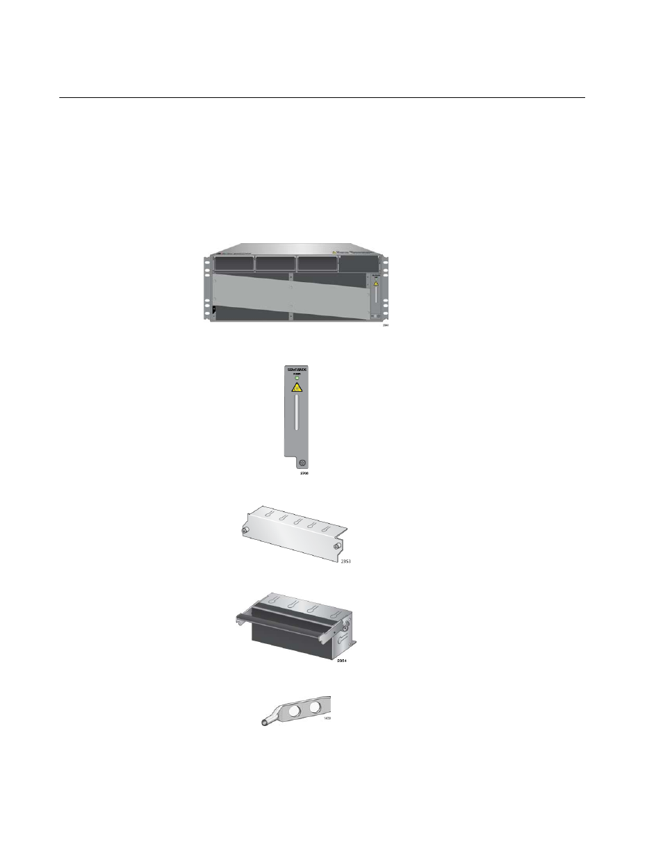
Figure 32. Components of the AT-SBx8106 Chassis
One AT-SBx8106 Chassis
One AT-SBxFAN06 Module pre-
installed in the vertical slot on
the right side of the front panel
Four blank line card slot covers
Three blank power supply slot
covers pre-installed in power
supply slots A to C on the front
panel
One grounding lug pre-installed
in the lower left corner on the
back panel