2 comma separated ascii, 4 storage module, 1 storage module addressing – Campbell Scientific CR10X Measurement and Control System User Manual
Page 68
SECTION 4. EXTERNAL STORAGE PERIPHERALS
4-4
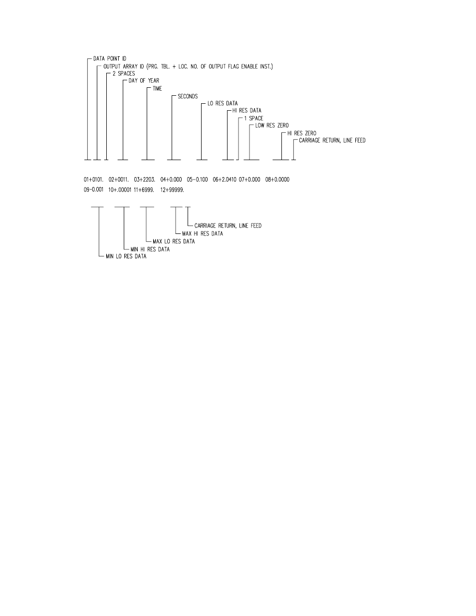
FIGURE 4.3-1. Example of CR10X Printable ASCII Output Format
4.3.2 COMMA SEPARATED ASCII
Comma Separated ASCII strips all IDs, leading
zeros, unnecessary decimal points and trailing
zeros, and plus signs. Data points are separated
by commas. Arrays are separated by Carriage
Return Line Feed. Comma Separated ASCII
requires approximately 6 bytes per data point.
Example:
1,234,1145,23.65,-12.26,625.9
1,234,1200,24.1,-10.98,650.3
4.4 STORAGE MODULE
The CR10X supports the SM4M/16M,
SM192/716, and CSM1 Storage Modules. The
Storage Module stores data in battery backed
RAM. Operating power is supplied by the
CR10X over pin 1 of the 9-pin connector.
Whenever power is applied to the 9-pin
connector (after having been off), the Storage
Module places a File Mark in the data (if a File
Mark is not the last data point already in
storage).
The File Mark separates data. For example, if
you retrieve data from one CR10X, disconnect
the Storage Module and connect it to a second
CR10X, a File Mark is automatically placed in
the data. This mark follows the data from the
first CR10X but precedes the data from the
second.
4.4.1 STORAGE MODULE ADDRESSING
The CSM1 does not support individual addresses.
Use address 1 when sending data to the CSM1.
The SM4M/16M and SM192/716 Storage Modules
can have individual addresses. Different addresses
allow 1) multiple Storage Modules to be connected to
the CR10X during on-line output, 2) different data to
be output to different Modules, and 3) transfer of
data from a Module that is left with the CR10X to a
Module that is hand carried to the site for data
transfer (
∗9 Mode).
Storage Modules are assigned addresses (1-8) either
through the
∗9 Mode or with the SMCOM or SMS
software. 1 is the default address when the Storage
Module is reset. Unless you are using one of the
features which require different addresses, you need
not assign any other address.
Address 1 is also a universal address when
sending data or commands to a storage module
with Instruction 96,
∗8, or ∗9. When address 1
is entered in the
∗9 Mode (default) or in the
device code (71, Table 4.2-1) for Instruction 96
or the
∗8 Mode, The CR10X searches for the
Storage Module with the lowest address that is
not full (fill and stop configuration only) and
addresses it. In other words, if a single Storage
Module is connected, and it is not full, address 1