Configuration 5, B.5 input data filters – Campbell Scientific CR10X Measurement and Control System User Manual
Page 238
APPENDIX B. CONTROL PORT SERIAL I/O INSTRUCTION 15
B-6
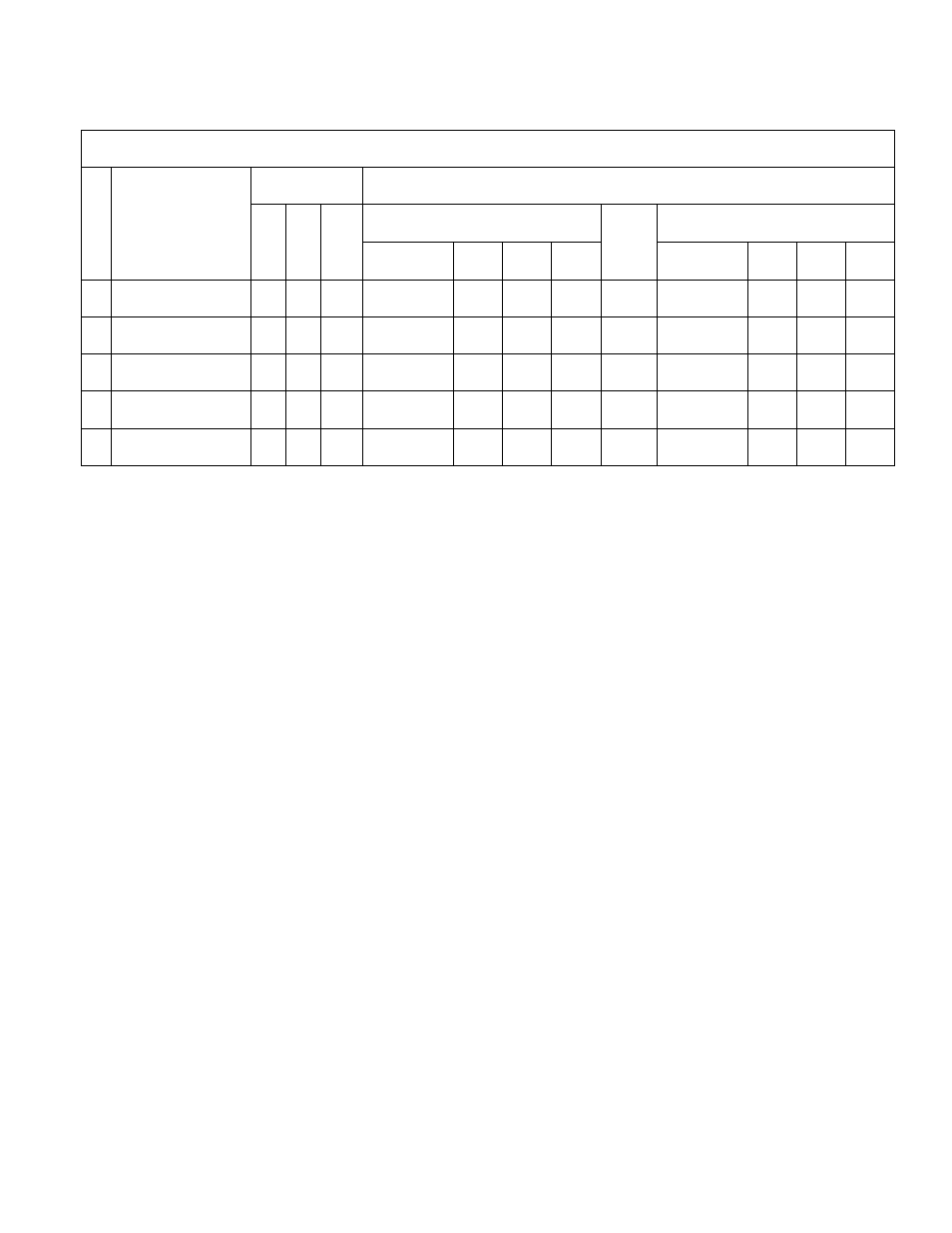
TABLE B-1. Input/Output Configurations
Parameters
Port Functions
Single-digit Parameter 4 (C)
Double-digit Parameter 4 (AB)
#
Configuration
3
6
8
RTS/DTR
CTS
TX
RX
Qty
Ports
Used
RTS/DTR
CTS
TX
RX
1
DTR,RX
x
0
nz
C
nc
nc
C+1
2
B
nc
nc
A
2
DTR,TX
nz
nz
0
C
nc
C+1
nc
2
B
nc
A
nc
3
DTR,CTS,TX
0
nz
0
C
C+1
C+2
nc
3
B
B+1
A
nc
4
DTR,TX, RX
nz
nz
nz
C
nc
C+1
C+2
3
B
nc
A
A+1
5
DTR,CTS,TX,RX
0
nz
nz
C
C+1
C+2
C+3
4
B
B+1
A
A+1
nz
=
non-zero number
TX
=
serial output
x
=
don't care
RX
=
serial input
nc
=
not connected
RTS/DTR
=
Request to Send /Data Terminal Ready
C
=
first control port (single-digit Parameter 4)
CTS
=
Clear to Send
A
=
TX or RX port (double-digit Parameter 4)
Parameter 3
=
CTS/Delay before send
B
=
control port (double-digit Parameter 4)
Parameter 6
=
Number of Locations to Send
Parameter 8
=
Maximum number of characters to receive
"C" is incremented for each repetition by the “No. of Ports Used"
“A” and “B” are incremented for each repetition by the number of TX and RX ports used and the number of
RTS/DTR and CTS ports used respectively.
CONFIGURATION 5
Serial data are output and serial data received
by the CR10X. The CTS line is used.
Parameter 3 must be zero while Parameters 6
and 8 must be greater than zero. A single-digit
Parameter 4 specifies the control port used for
the RTS/DTR line, the next port is for CTS, and
the third and fourth ports are for Serial Output
and Serial Input, respectively. With a double-
digit Parameter 4, the first digit specifies the
consecutive Serial Output and Serial Input lines
and the second digit specifies the consecutive
RTS/DTR and CTS lines. A total of 4 control
ports are used per repetition.
B.5 INPUT DATA FILTERS.
P15 supports search filters strings that can be
applied to a received data set. It is typically
used locate the beginning of the desired data
set. Multiple filters can be applied if the data is
imbedded in a long string. To implement a filter
string follow P15 immediately with either
instructions P63 or P68 (both of which are
extended parameter instructions). Multiple use
of these instructions can be used if the search
string is longer than 8 characters. Separate
different types of filter strings with a null
character (00). Once the first string has been
found and the data decoded and loaded into
input locations the next sequential string loaded
into P63 or P68 (after the 00) will be used for
any other incoming data. If the filter string is not
found -99999 will be stored in the input location.
Once the last string has been found and the
data decoded and loaded into input locations,
the first string loaded will be used again.
Enter the actual filter/search string by keying the
decimal equivalent of the ASCII character (see
Appendix E. of the CR10X Operators Manual).
Example: GPS receiver program
A common application with P15 is to read in
data from a GPS receiver. The GPS receivers