5 switch closures on control ports (rain gage) – Campbell Scientific CR10X Measurement and Control System User Manual
Page 113
SECTION 8. PROCESSING AND PROGRAM CONTROL EXAMPLES
8-5
INPUT LOCATIONS
1 Ref_Temp
12 TC_#11
23 Soil_#6
2 TC_#1
13 TC_#12
24 Soil_#7
3 TC_#2
14 TC_#13
25 Soil_#8
4 TC_#3
15 TC_#14
26 Soil_#9
5 TC_#4
16 TC_#15
27 Soil_#10
6 TC_#5
17 TC_#16
28 Soil_#11
7 TC_#6
18 Soil_#1
29 Soil_#12
8 TC_#7
19 Soil_#2
30 Soil_#13
9 TC_#8
20 Soil_#3
31 Soil_#14
10 TC_#9
21 Soil_#4
32 Soil_#15
11 TC_#10
22 Soil_#5
33 Soil_#16
8.4 SUB 1 MINUTE OUTPUT INTERVAL
SYNCHED TO REAL TIME
Output can be synchronized to seconds by
pressing “-” or “C” while entering the first
parameter in Instruction 92. If a counter,
incremented within the program, was used to
determine when to set the Output Flag, output
would depend on the number of times the table
was executed. The actual time of output would
depend on when the program was actually
compiled and started running. If the table
overran its execution interval (Section 1.1.1),
the output interval would not be the count
multiplied by the execution interval, but some
longer interval.
In this example a temperature (107
Temperature Probe) is measured every 0.5
seconds and the average output every 30
seconds.
PROGRAM
*
Table 1 Program
01:
0.5
Execution Interval (seconds)
01:
Internal Temperature (P17)
1:
1
Loc [ Ref_Temp ]
02:
Thermocouple Temp (DIFF) (P14)
1:
1
Reps
2: 11
±2.5 mV Fast Range
3:
2
DIFF Channel
4:
2
Type E (Chromel-Constantan)
5:
1
Ref Temp Loc [ Ref_Temp ]
6:
2
Loc [ TC_Temp ]
7:
1
Mult
8:
0
Offset
03:
If time is (P92)
1:
0--
Minutes (Seconds --) into a
2: 30
Interval (same units as above)
3: 10
Set Output Flag High
04:
Average (P71)
1:
1
Reps
2:
2
Loc [ TC_Temp ]
INPUT LOCATIONS
1 Ref_Temp
2 TC_Temp
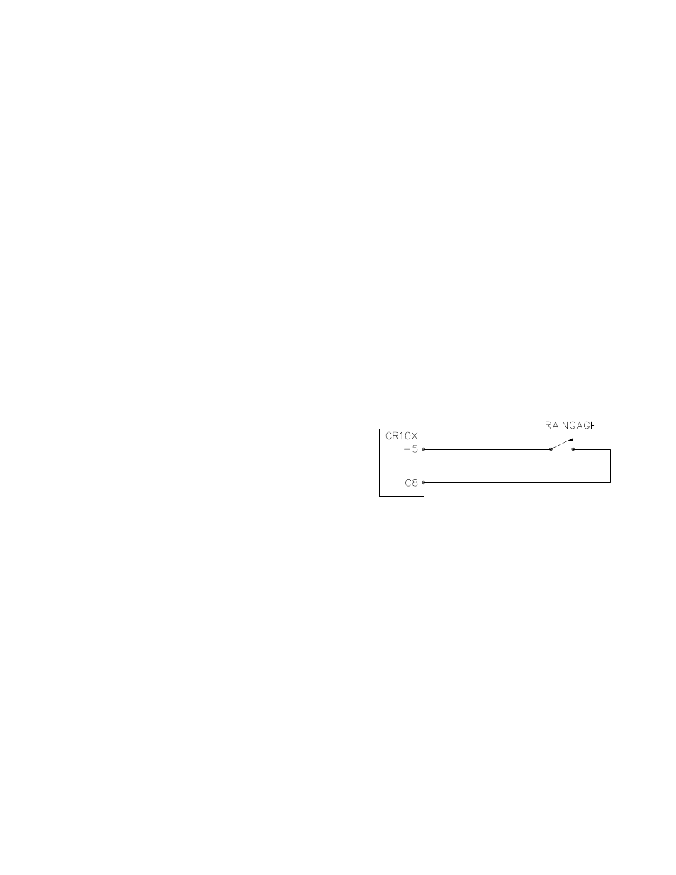
8.5 SWITCH CLOSURES ON CONTROL
PORTS (RAIN GAGE)
Control ports 6, 7, and 8 can be used to
measure switch closures up to 40 Hz.
Instruction 3, pulse, is used to measure two rain
gages on pulse inputs 1 and 2, and a third rain
gage with control port 8. This is done as a
comparison. In a real application the pulse
channels would be used for wind speed and a
control port for a rain gage. The rain gage is
connected as diagrammed below.
FIGURE 8.5-1. Connections for Rain Gage
PROGRAM
*
Table 1 Program
01:
10.0
Execution Interval (seconds)
01:
Pulse (P3)
1:
2
Reps
2:
1
Pulse Input Channel
3:
2
Switch Closure
4:
10
Loc [ Precip_1 ]
5:
.254
Mult
6:
0
Offset
02:
Pulse (P3)
1:
1
Reps
2:
8
Control Port
3:
2
Switch Closure
4:
12
Loc [ Precip_3 ]
5:
.254
Mult
6:
0
Offset