1336-series drive control logic chart, Allen-bradley 1336-series ac drives, Table 54 – Alliance Laundry Systems 160 User Manual
Page 96
Allen-Bradley 1336-Series AC Drives
F232120
94
© Copyright, Alliance Laundry Systems LLC – DO NOT COPY or TRANSMIT
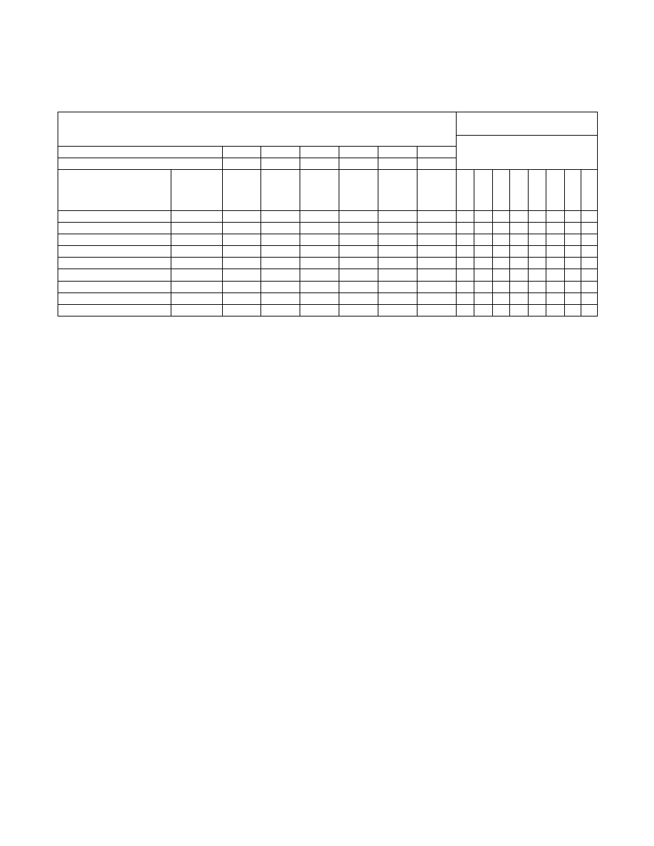
1336-Series Drive Control Logic Chart
Cabinet Hardmount
A Control and V Control
H – Control Voltage High (greater than 10V DC)
L – Control Voltage Low (less than 1V DC)
0 = No signal received
1 = Signal received
SW2
SW1
SW3
Rev
Stop
Fwd
Input Status – Parameter 55
DC Volt Meter Red Probe Terminal Location
27
28
26
22
20
19
DC Volt Meter Black Probe Terminal Location
29
29
29
29
29
29
Action
Frequency
Preset
Parameter #
Terminal
#27
(SW2)
Terminal
#28
(SW1)
Terminal
#26
(SW3)
Terminal
#22
(STR)
Terminal
#20
(Stop)
Terminal
#19
(STF)
SW2
SW1
SW3
A
u
x
ili
ar
y
Rev (STR)
Not Us
e
d
St
o
p
Fw
d (STF)
Idle
N/A
H
H
H
H
L/H
H
0
0
0
1
0
0
0/1
0
1/2 Wash Speed Forward
73
H
H
L
H
L
L
0
0
1
1
0
0
1
1
1/2 Wash Speed Reverse
73
H
H
L
L
L
H
0
0
1
1
1
0
1
0
Wash Speed Forward
28
L
H
H
H
L
L
1
0
0
1
0
0
1
1
Wash Speed Reverse
28
L
H
H
L
L
H
1
0
0
1
1
0
1
0
Distribution Speed
27
H
L
H
H
L
L
0
1
0
1
0
0
1
1
Spin 1
75
L
H
L
H
L
L
1
0
1
1
0
0
1
1
Spin 2
29
L
L
H
H
L
L
1
1
0
1
0
0
1
1
Spin 3
74
H
L
L
H
L
L
0
1
1
1
0
0
1
1
Table 54