160 series drive control logic chart, Allen-bradley 160-series ac drives, Table 28 – Alliance Laundry Systems 160 User Manual
Page 46
Allen-Bradley 160-Series AC Drives
F232120
44
© Copyright, Alliance Laundry Systems LLC – DO NOT COPY or TRANSMIT
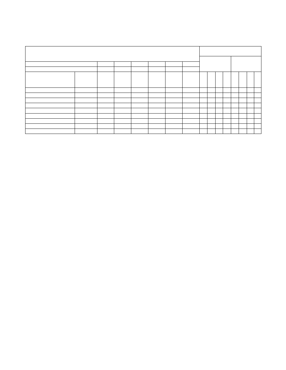
160 Series Drive Control Logic Chart
Cabinet Hardmount
A Control, B control, V control and EDC/Netmaster control
H – Control Voltage High (greater than 10V DC)
L – Control Voltage Low (less than 1V DC)
0 = No signal received
1 = Signal received
SW3
SW2
SW1
STF
Stop
STR
Preset Status –
Parameter 15
Input Status –
Parameter 12
DC Volt Meter Red Probe Terminal Location
4
2
1
6
8
5
DC Volt Meter Black Probe Terminal Location
3
3
3
3
3
3
Action
Frequency
Preset
Parameter #
Terminal
#4
(SW3)
Terminal
#2
(SW2)
Terminal
#1
(SW1)
Terminal
#6
(STF)
Terminal
#8
(Stop)
Terminal
#5
(STR)
Not Us
e
d
SW3
SW2
SW1
Not Us
e
d
STF
St
o
p
STR
Idle
N/A
H
H
H
H
L/H
H
0
0
0
0
0
0
0/1
0
1/2 Wash Speed Forward
62
H
H
L
L
L
H
0
0
0
1
0
1
1
0
1/2 Wash Speed Reverse
62
H
H
L
H
L
L
0
0
0
1
0
0
1
1
Wash Speed Forward
63
H
L
H
L
L
H
0
0
1
0
0
1
1
0
Wash Speed Reverse
63
H
L
H
H
L
L
0
0
1
0
0
0
1
1
Distribution Speed
65
L
H
H
L
L
H
0
1
0
0
0
1
1
0
Spin 1
64
H
L
L
L
L
H
0
0
1
1
0
1
1
0
Spin 2
67
L
L
H
L
L
H
0
1
1
0
0
1
1
0
Spin 3
66
L
H
L
L
L
H
0
1
0
1
0
1
1
0
Table 28