Table 50 – Alliance Laundry Systems 160 User Manual
Page 93
Allen-Bradley 1336-Series AC Drives
91
F232120
© Copyright, Alliance Laundry Systems LLC – DO NOT COPY or TRANSMIT
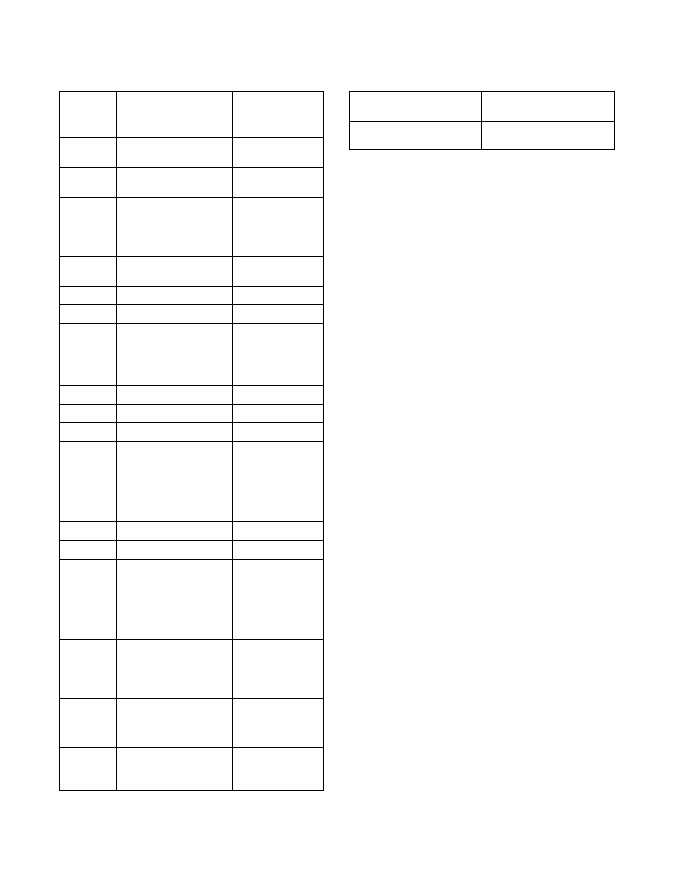
Control Terminal Block Designations
Table 50
Torque Specifications
Terminal
Number
Signal
Machine Use
TE
True Earth
Not Used
1, 2, 3
External Speed Pot
Select Machines
Only
4
Signal Common
Specialty
Machines Only
5
0 – 10V DC Input
Specialty
Machines Only
6
4 – 20 mA Input
Specialty
Machines Only
7, 8
Pulse Input for
Frequency
Specialty
Machines Only
9
Analog Output
Not Used
10, 11
Programmable Contact
Not Used
11, 12
Run Contact
Not Used
13, 14
Fault Contact NO
Fault Indicator
Light (Some
Machines)
14, 15
Fault Contact NC
Not Used
16, 17
Alarm Contact NO
Balance Relay
17, 18
Alarm Contact NC
Not Used
A1, A2
Future Use
Not Used
19, 29
STF
Forward Motion
20, 21
Stop
Drive Balance
Switch Interlock
Relay or Jumper
21
Common
22, 29
STR
Reverse Motion
23, 21
Input
Not Used
24, 25
Input
Motor Thermal
Switch (Some
Machines)
25
Common
28, 29
SW1
Preset Speed Input
#1
27, 29
SW2
Preset Speed Input
#2
26, 29
SW3
Preset Speed Input
#3
29
Common
30, 29
Enable
Balance Switch,
Drive Interlock or
Jumper
Max/Min Wire Size
mm
2
(AWG)
Maximum Torque
N-m (lb-in)
2.1/0.3
(14/22)
1.36
(12)
Table 51