160 series drive control logic chart, Allen-bradley 160-series ac drives, Table 30 – Alliance Laundry Systems 160 User Manual
Page 48
Allen-Bradley 160-Series AC Drives
F232120
46
© Copyright, Alliance Laundry Systems LLC – DO NOT COPY or TRANSMIT
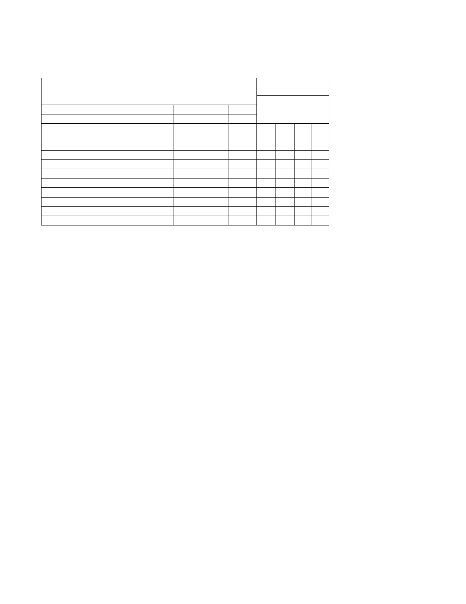
160 Series Drive Control Logic Chart
Pocket Hardmount - IPH, IP and CP Models
PS40 control
H – Control Voltage High (greater than 10V DC)
L – Control Voltage Low (less than 1V DC)
0 = No signal received
1 = Signal received
Fwd
Stop
Rev
Control Input Status –
Parameter 12
DC Volt Meter Red Probe Terminal Location
06
08
05
DC Volt Meter Black Probe Terminal Location
03
03
03
Action
Terminal
#06
(STF)
Terminal
#08
(Stop)
Terminal
#05
(STR)
Not Used
STF
St
o
p
STR
Idle
H
L
H
0
0
1
0
Wash Speed Forward
L
L
H
0
1
1
0
Wash Speed Reverse
H
L
L
0
0
1
1
Distribution Speed
L
L
H
0
1
1
0
Low Spin Speed
L
L
H
0
1
1
0
Medium Spin Speed
L
L
H
0
1
1
0
High Spin Speed
L
L
H
0
1
1
0
SmartSpin
L
L
L
0
1
1
1
NOTE: These models use analog signals to control speed – refer to parameter #6 (command freq.) and parameter #16 (analog
input %) to verify speed input signal.
Table 30