Table 11 – Alliance Laundry Systems 160 User Manual
Page 19
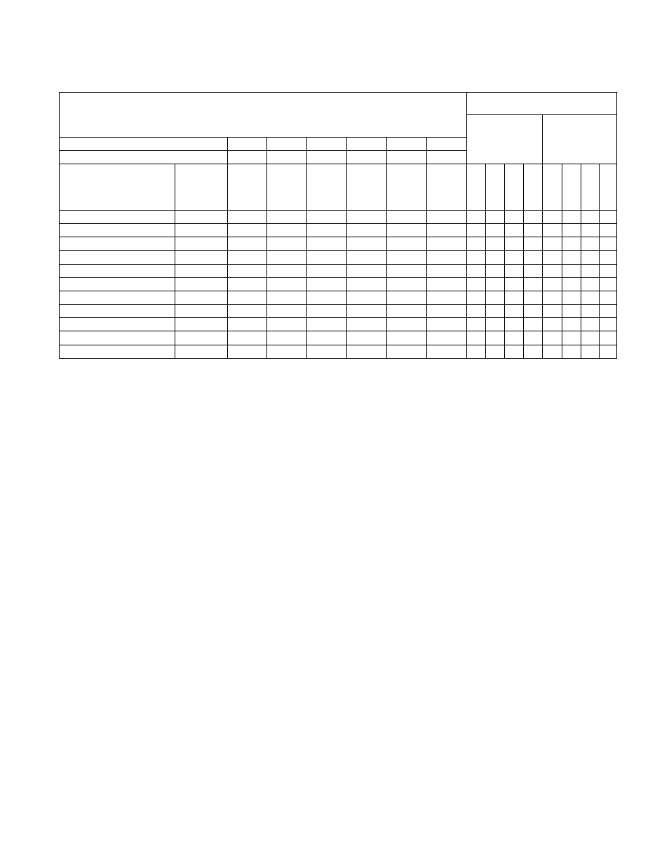
PowerFlex 40 and 400 Drive Control Logic
17
F232120
© Copyright, Alliance Laundry Systems LLC – DO NOT COPY or TRANSMIT
Pocket Hardmount
WE-6 control - Design 6, 7 and 8
H – Signal Voltage High (approximately 24V DC)
L – Signal Voltage Low (less than 1V DC)
0 = No signal received
1 = Signal received
Digital
In 3
Digital
In 2
Digital
In 1
Stop
Rev
Fwd
Digital Input
Status – Parameter
d014
Control Input
Status – Parameter
d013
DC Volt Meter Red Probe Terminal Location
07
06
05
01
03
02
DC Volt Meter Black Probe Terminal Location
04
04
04
04
04
04
Action
Frequency
Preset
Parameter #
Terminal
#07
(SW3)
Terminal
#06
(SW2)
Terminal
#05
(SW1)
Terminal
#01
(Stop)
Terminal
#03
(STR)
Terminal
#02
(STF)
*Dig
it
a
l In
4
Digit
a
l In
3
(SW3
)
Digit
a
l In
2
(SW2
)
Digit
a
l In
1
(SW1
)
DB
T
ra
n
s
On
St
o
p
Rev (S
T
R
)
Fwd
(STF)
Idle
N/A
H
H
H
L/H
H
H
0
0
0
0
0
0/1
0
0
1/2 Wash Speed Forward
70
H
H
H
L
H
L
*1
0
0
0
0
1
0
1
1/2 Wash Speed Reverse
70
H
H
H
L
L
H
0
0
0
0
0
1
1
0
Wash Speed Forward
72
H
L
H
L
H
L
*1
0
1
0
0
1
0
1
Wash Speed Reverse
72
H
L
H
L
L
H
0
0
1
0
0
1
1
0
Distribution Speed
71
H
H
L
L
H
L
*1
0
0
1
0
1
0
1
Medium Extract/Spray Rinse
76
L
L
H
L
H
L
*1
1
1
0
0
1
0
1
Extract Speed 1
75
L
H
L
L
H
L
*1
1
0
1
0
1
0
1
Extract Speed 2
73
H
L
L
L
H
L
*1
0
1
1
0
1
0
1
Extract Speed 3 (default)
77
L
L
L
L
H
L
*1
1
1
1
0
1
0
1
Extract Speed 3 (maximum)
74
L
L
H
L
H
L
*1
1
0
0
0
1
0
1
*If digital in 4 is wired to the Forward Input terminal #02, this input will be a “1” whenever the drive receives a forward command. Disregard otherwise.
Table 11