1305-series drive control logic chart, Table 42 – Alliance Laundry Systems 160 User Manual
Page 71
Allen-Bradley 1305-Series AC Drives
69
F232120
© Copyright, Alliance Laundry Systems LLC – DO NOT COPY or TRANSMIT
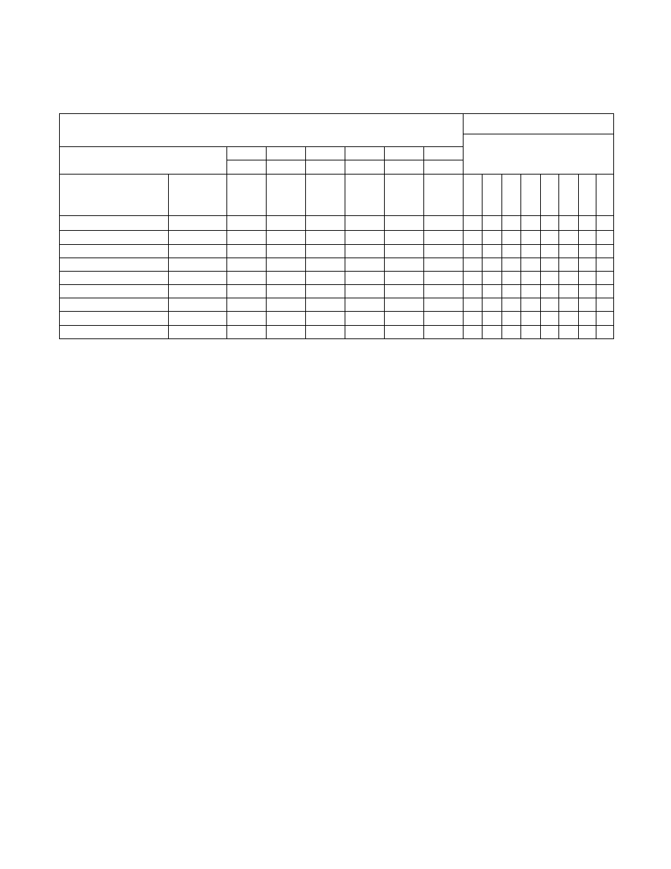
1305-Series Drive Control Logic Chart
Cabinet Hardmount
V-Control and EDC/Netmaster Control
H – Control Voltage High (approximately 5V DC)
L – Control Voltage Low (less than 1V DC)
0 = No Signal Received
1 = Signal Received
SW3
SW2
SW1
Rev
Stop
Fwd
Input Status - Parameter #55
DC Volt Meter Red Probe Terminal Location
18
17
16
13
8
6
DC Volt Meter Black Probe Terminal Location
7
7
7
7
7
7
Action
Frequency
Preset
Parameter
Terminal
#18
(SW3)
Terminal
#17
(SW2)
Terminal
#16
(SW1)
Terminal
#13
(STR)
Terminal
#8
(Stop)
Terminal
#6
(STF)
Not Used
SW
3
SW
2
SW
1
Not Used
Re
v (
S
TR)
St
o
p
F
w
d (
S
TF
)
Idle
N/A
H
H
H
H
L/H
H
0
0
0
0
0
0
0/1
0
1/2 Wash Speed Forward
27
H
H
L
H
L
L
0
0
0
1
0
0
1
1
1/2 Wash Speed Reverse
27
H
H
L
L
L
H
0
0
0
1
0
1
1
0
Wash Speed Forward
28
H
L
H
H
L
L
0
0
1
0
0
0
1
1
Wash Speed Reverse
28
H
L
H
L
L
H
0
0
1
0
0
1
1
0
Distribution Speed
73
L
H
H
H
L
L
0
1
0
0
0
0
1
1
Spin 1
29
H
L
L
H
L
L
0
0
1
0
0
0
1
1
Spin 2
75
L
L
H
H
L
L
0
1
1
0
0
0
1
1
Spin 3
74
L
H
L
H
L
L
0
1
0
1
0
0
1
1
Table 42