Alliance Laundry Systems 160 User Manual
Page 25
PowerFlex 40 and 400 Drive Control Logic
23
F232120
© Copyright, Alliance Laundry Systems LLC – DO NOT COPY or TRANSMIT
Control Wire
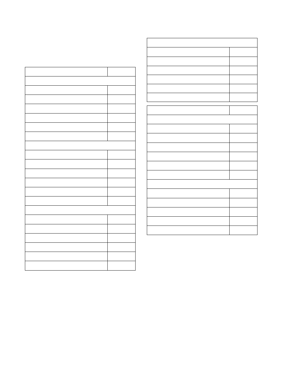
During troubleshooting, if the wire path between the
control board and the drive is uncertain, refer to
Table 15 for wire connection numbers.
Control Wire Connection Reference Table.
Table 15
Output Board Terminal
V-Control F370314, F8206501 and F370447-6, etc.
STF
02
STR
03
RH
07
RM
06
RL
05
COM
04
WE-6 Interface Board P/N: F370577, F0370446-xx
J2A-30
04
J2A-31
06
J2A-32
02
J2A-33
07
J2A-34
05
J2A-35
03
EDC – Output Board P/N: F370433
H2-7
07
H2-8
06
H2-9
05
H2-10
04
H2-11
03
H2-12
02
Table 15 (continued)
Table 15 (continued)
UniLinc Control– Output Board F8108001
H13-2
04
H13-3
07
H13-4
06
H13-5
05
H13-6
03
H13-7
02
Output Board Terminal
A and B-Control P/N: F0370448xx
J11-1-8/STF
02
J11-1-7/STR
03
J11-1-6/RH
07
J11-1-5/RM
06
J11-1-4/RL
03
J11-1-3/COM
04
PS40 Main Board P/N: C000281
C12 OV, R-, L-
01, 04, 14
C12 0-10v
13
C12 R+
02
C12 L+
03
Jumper
N/A