Powerflex 40 drive control logic chart, Table 9 – Alliance Laundry Systems 160 User Manual
Page 17
PowerFlex 40 and 400 Drive Control Logic
15
F232120
© Copyright, Alliance Laundry Systems LLC – DO NOT COPY or TRANSMIT
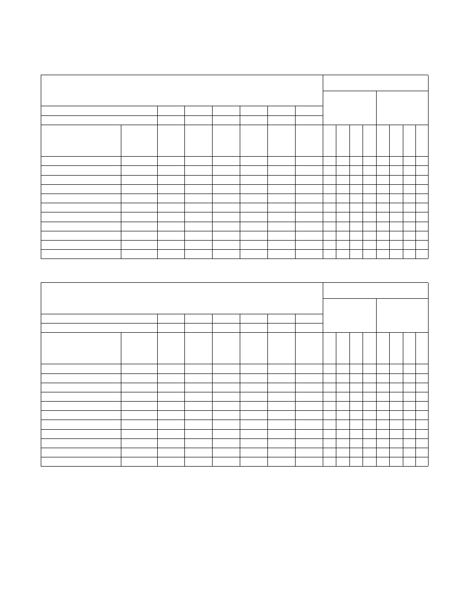
PowerFlex 40 Drive Control Logic Chart
Table 9
Pocket Hardmount - 35 lb through 125 lb Capacity
UniLinc control and M30 control
H – Signal Voltage High (approximately 24V DC)
L – Signal Voltage Low (less than 1V DC)
0 = No signal received
1 = Signal received
Digital
In 3
Digital
In 2
Digital
In 1
Stop
Rev
Fwd
Digital Input
Status – Parameter
d014
Control Input
Status – Parameter
d013
DC Volt Meter Red Probe Terminal Location
07
06
05
01
03
02
DC Volt Meter Black Probe Terminal Location
04
04
04
04
04
04
Action
Frequency
Preset
Parameter #
Terminal
#07
Terminal
#06
Terminal
#05
Terminal
#01
Terminal
#03
Terminal
#02
Di
git
a
l I
n
4
Digit
a
l In
3
Di
git
a
l I
n
2
Digit
a
l In
1
D
B
T
rans
On
St
o
p
Rev
Fwd
Idle
N/A
H
H
H
L/ H
H
H
0
0
0
0
0
0/1
0
0
Reduced Wash Speed (cw)
70
H
H
H
L
H
L
0
0
0
0
0
1
0
1
Reduced Wash Speed (ccw)
70
H
H
H
L
L
H
0
0
0
0
0
1
1
0
Wash Speed (cw)
72
H
L
H
L
H
L
0
0
1
0
0
1
0
1
Wash Speed (ccw)
72
H
L
H
L
L
H
0
0
1
0
0
1
1
0
Distribution Speed (cw)
71
H
H
L
L
H
L
0
0
0
1
0
1
0
1
Extract Speed 1 (ccw)
76
L
L
H
L
H
L
0
1
1
0
0
1
0
1
Extract Speed 2 (ccw)
75
L
H
L
L
H
L
0
1
0
1
0
1
0
1
Extract Speed 3 (ccw)
73
H
L
L
L
H
L
0
0
1
1
0
1
0
1
Extract Speed 4 (ccw)
77
L
L
L
L
H
L
0
1
1
1
0
1
0
1
Extract Speed 5 (ccw)
74
L
H
H
L
H
L
0
1
0
0
0
1
0
1
Pocket Hardmount - 150 Capacity
Terminator control Control
H – Signal Voltage High (approximately 24V DC)
L – Signal Voltage Low (less than 1V DC)
0 = No signal received
1 = Signal received
Digital
In 3
Digital
In 2
Digital
In 1
Stop
Rev
Fwd
Digital Input
Status – Parameter
d014
Control Input
Status – Parameter
d013
DC Volt Meter Red Probe Terminal Location
07
06
05
01
03
02
DC Volt Meter Black Probe Terminal Location
04
04
04
04
04
04
Action
Frequency
Preset
Parameter #
Terminal
#07
Terminal
#06
Terminal
#05
Terminal
#01
Terminal
#03
Terminal
#02
D
igit
a
l I
n
4
D
igit
a
l In 3
D
igit
a
l I
n
2
D
igit
a
l In 1
DB T
rans
On
St
o
p
Re
v
Fw
d
Idle
N/A
H
H
H
L/H
H
H
0
0
0
0
0
0/1
0
0
Reduced Wash speed (ccw)
70
H
H
H
L
L
H
0
0
0
0
0
1
1
0
Reduced Wash Speed (cw)
70
H
H
H
L
H
L
0
0
0
0
0
1
0
1
Wash Speed (ccw)
72
H
L
H
L
L
H
0
0
1
0
0
1
1
0
Wash Speed (cw)
72
H
L
H
L
H
L
0
0
1
0
0
1
0
1
Distribution Speed (ccw)
71
H
H
L
L
L
H
0
0
0
1
0
1
1
0
Very Low Extract (ccw)
76
L
L
H
L
L
H
0
1
1
0
0
1
1
0
Low Extract (ccw)
75
L
H
L
L
L
H
0
1
0
1
0
1
1
0
Medium Extract (ccw)
73
H
L
L
L
L
H
0
0
1
1
0
1
1
0
High Extract (ccw)
77
L
L
L
L
L
H
0
1
1
1
0
1
1
0
Very High Extract (ccw)
74
L
H
H
L
L
H
0
1
0
0
0
1
1
0