Table 12, Table 13 – Alliance Laundry Systems 160 User Manual
Page 20
PowerFlex 40 and 400 Drive Control Logic
F232120
18
© Copyright, Alliance Laundry Systems LLC – DO NOT COPY or TRANSMIT
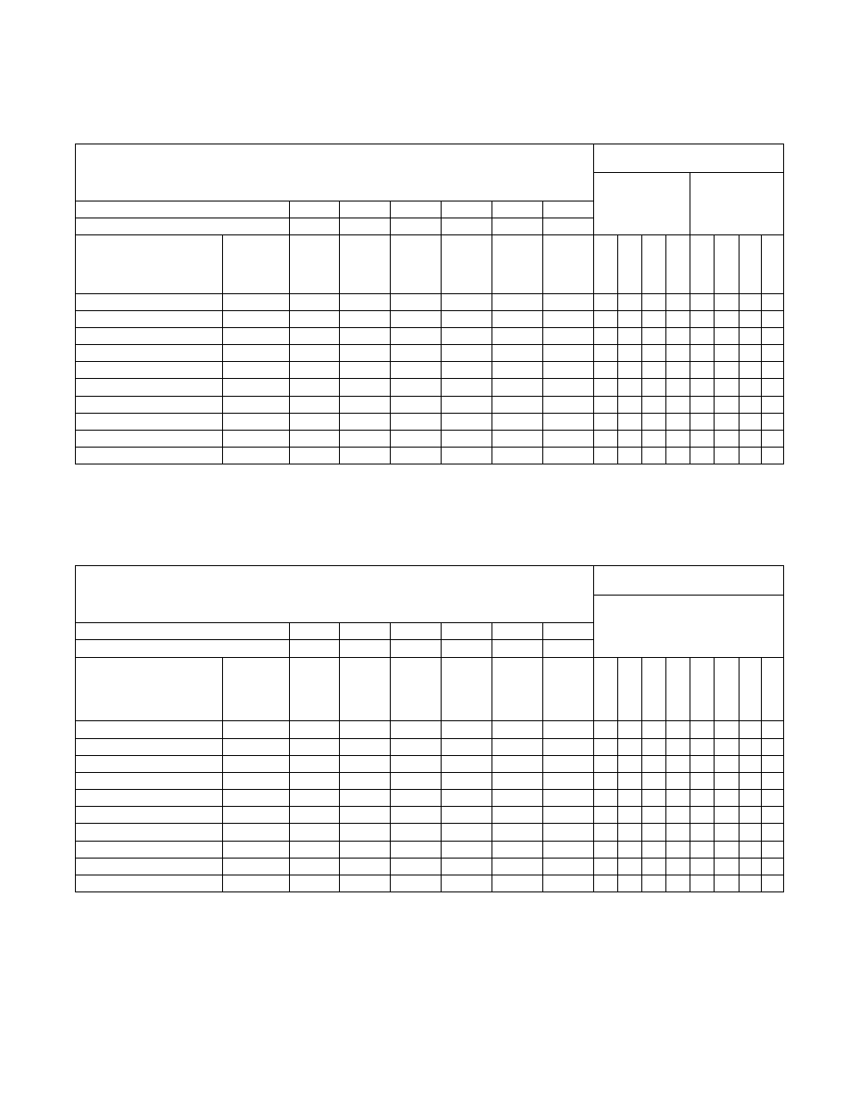
PowerFlex 40 Drive Control Logic Chart
PowerFlex 400 Drive Control Logic Chart
Cabinet Freestanding
WE-6 control
H – Signal Voltage High (approximately 24V DC)
L – Signal Voltage Low (less than 1V DC)
0 = No signal received
1 = Signal received
Digital
In 3
Digital
In 2
Digital
In 1
Stop
Rev
Fwd
Digital Input
Status – Parameter
d014
Control Input
Status – Parameter
d013
DC Volt Meter Red Probe Terminal Location
07
06
05
01
03
02
DC Volt Meter Black Probe Terminal Location
04
04
04
04
04
04
Action
Frequency
Preset
Parameter #
Terminal
#07
(SW3)
Terminal
#06
(SW2)
Terminal
#05
(SW1)
Terminal
#01
(Stop)
Terminal
#03
(STR)
Terminal
#02
(STF)
*Di
g
it
a
l I
n
4
Digi
ta
l In 3
(SW3)
Digi
ta
l In 2
(SW2)
Digi
ta
l In 1
(SW1)
DB T
rans
On
St
o
p
Rev (STR)
Fw
d (STF)
Idle
N/A
H
H
H
L/H
H
H
0
0
0
0
0
0/1
0
0
1/2 Wash Speed Forward
74
L
H
H
L
H
L
*1
1
0
0
0
1
0
1
1/2 Wash Speed Reverse
74
L
H
H
L
L
H
0
1
0
0
0
1
1
0
Wash Speed Forward
72
H
L
H
L
H
L
*1
0
1
0
0
1
0
1
Wash Speed Reverse
72
H
L
H
L
L
H
0
0
1
0
0
1
1
0
Distribution Speed
71
H
H
L
L
H
L
*1
0
0
1
0
1
0
1
Medium Extract
76
L
L
H
L
H
L
*1
1
1
0
0
1
0
1
High 1 Extract
75
L
H
L
L
H
L
*1
1
0
1
0
1
0
1
High 2 Extract
73
H
L
L
L
H
L
*1
0
1
1
0
1
0
1
High 3 Extract
77
L
L
L
L
H
L
*1
1
1
1
0
1
0
1
*If digital in 4 is wired to the Forward Input terminal #02, this input will be a “1” whenever the drive receives a forward command. Disregard otherwise.
Table 12
Cabinet Freestanding (250 Model Only)
WE-6 control
H – Signal Voltage High (greater than 10V DC)
L – Signal Voltage Low (less than 1V DC)
0 = No signal received
1 = Signal received
Digital
In 3
Digital
In 2
Digital
In 1
Fwd
Stop
Rev
Control Input Status – Parameter d302
DC Volt Meter Red Probe Terminal Location
07
06
05
02
01
03
DC Volt Meter Black Probe Terminal Location
04
04
04
04
04
04
Action
Frequency
Preset
Parameter #
Terminal
#07
(SW3)
Terminal
#06
(SW2)
Terminal
#05
(SW1)
Terminal
#02
(STF)
Terminal
#01
(Stop)
Terminal
#03
(STR)
Not U
s
ed
*Di
g
it
a
l
In
4
Digi
ta
l In 3
(S
W
3
)
Digi
ta
l In 2
(S
W
2
)
Digi
ta
l In 1
(S
W
1
)
St
o
p
Rev (STR)
Fw
d (STF)
Idle
N/A
H
H
H
H
L or H
H
0
0
0
0
0
0/1
0
0
1/2 Wash Speed Forward
355
L
H
H
L L
H
0
*1
1
0
0
1
0
1
1/2 Wash Speed Reverse
355
L
H
H
H
L
L
0
0
1
0
0
1
1
0
Wash Speed Forward
145
H
L
H
L L
H
0
*1
0
1
0
1
0
1
Wash Speed Reverse
145
H
L
H
H
L
L
0
0
0
1
0
1
1
0
Distribution Speed
144
H
H
L
L
L
H
0
*1
0
0
1
1
0
1
Medium Extract
357
L
L
H
L
L
H
0
*1
1
1
0
1
0
1
High 1 Extract
356
L
H
L
L
L
H
0
*1
1
0
1
1
0
1
High 2 Extract
146
H
L
L
L
L
H
0
*1
0
1
1
1
0
1
High 3 Extract
358
L
L
L
L
L
H
0
*1
1
1
1
1
0
1
*If digital in 4 is wired to the Forward Input terminal #02, this input will be a “1” whenever the drive receives a forward command. Disregard otherwise.
Table 13