Figure 40, Figure 40 . t, Refer to figure 40 – Alliance Laundry Systems 160 User Manual
Page 69
Allen-Bradley 1305-Series AC Drives
67
F232120
© Copyright, Alliance Laundry Systems LLC – DO NOT COPY or TRANSMIT
PHM665N
1
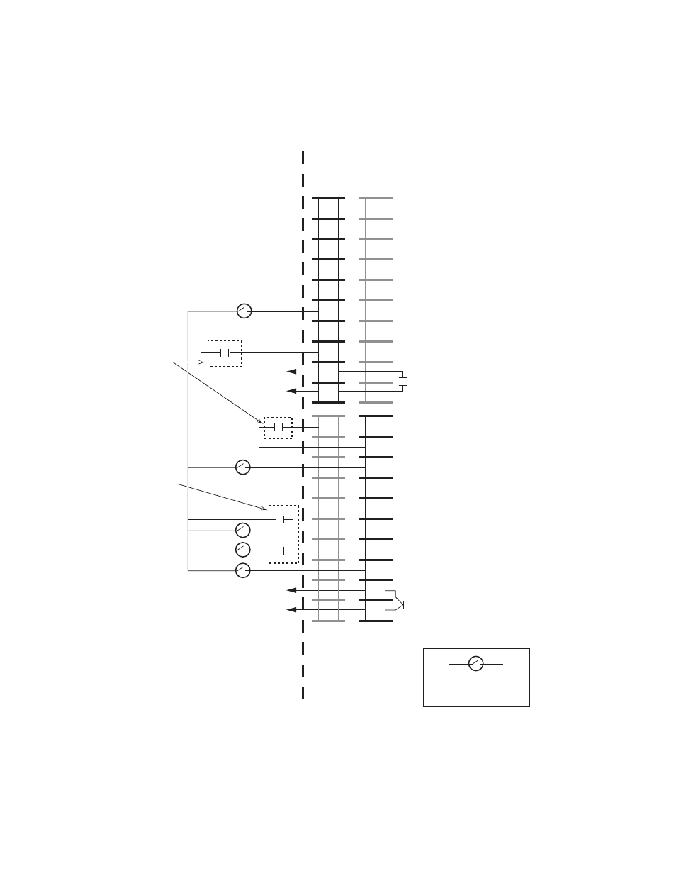
Jumper Balance Switch or Drive Interlock Relay
3
1/2 WashRelay on some machines
2
Jumper or Motor Overtemp Switch
4
Fault Indicator Light
Figure 40
1
2
3
4
5
6
7
8
9
10
11
12
13
14
15
16
17
18
19
20
TB2
STF - Start Forward
Common
Stop
Output - Balance Relay
Common
STR - Start Reverse
Unused
Common
SW1 - Preset Input 1
SW2 - Preset Input 2
SW3 - Preset Input 3
Enable
Solid State Switch or
Relay Contact
Output 2 - Solid State Switch (Sink)
Running Indication
1305
Drive Hardware
Input Mode = “UniMac” Parameter #21
Typical Configuration
Output Run
Indication
Output
Balance
Detection
1/2 Wash Relay
On Some Machines
Jumper,
Drive Interlock or
Out-of-Balance
Switch
Washer-Extractor
Control Hardware