5 parameters, P419 scaling of analog output 1, P420 digital input 1 – NORD Drivesystems BU0500 User Manual
Page 99
5 Parameters
BU 0500 GB-1013
99
NOTE: An overview of the scaling of the various setpoints can be found in Section 8.8.
Pos : 205 /Anleit ungen/5. / 6. Parametrier ung [BU 0500 / BU 0200]/ Par ameter/ P400-P499/ Paramet er P418 – List e der digit alen F unktionen der analog en Ausgänge @ 0\ mod_1327940847568_388. doc x @ 9743 @ 5 @ 1
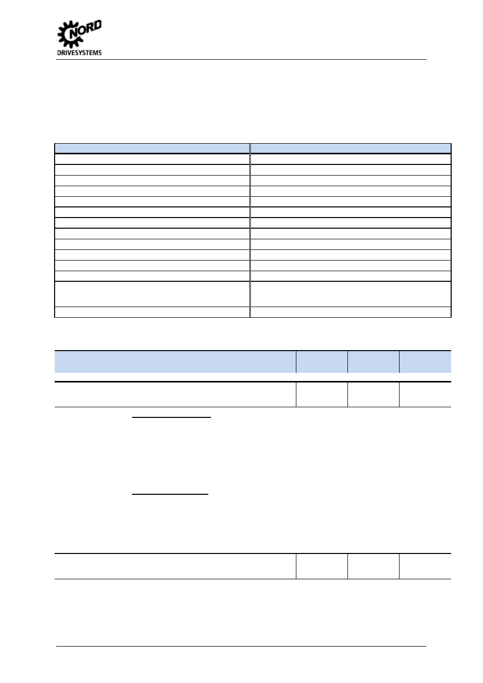
List of possible digital functions of the analog outputs
All relay functions described in parameter P434 can also be transferred via the analog output. If a
condition has been fulfilled, then there will be 10 V at the output terminals. Negation of the function
can be specified in parameter P419.
Value
Function
Value
Function
15
External brake
32
FI ready
16
Inverter working
33
Frequency and setpoint source
17
Current limit
34
... 40 reserved (POSICON
à BU 0510)
18
Torque current limit
41
... 43 reserved
19
Frequency limit
44
BusIO In Bit 0
20
Setpoint reached
45
BusIO In Bit 1
21
Fault
46
BusIO In Bit 2
22
Warning
47
BusIO In Bit 3
23
Overcurrent warning
48
BusIO In Bit 4
24
Motor overtemperature warning
49
BusIO In Bit 5
25
Torque current limit active
50
BusIO In Bit 6
26
Value of P541
51
BusIO In Bit 7
27
Generator torque current limit
52
Value from Bus setpoint
Output via Bus (if P546, P547 or P548 = 19), BUS Bit 4
then controls the analog output.
28
... 29 reserved
60
reserved (PLC
à BU 0550)
Pos : 206 /Anleit ungen/5. / 6. Parametrier ung [BU 0500 / BU 0200]/ Par ameter übersc hrift - Forts et zung Tabelle @ 1\ mod_1331566123473_388. doc x @ 18340 @ @ 1
Parameter
{factory setting}
Setting value / Description / Note
Supervisor
Parameter
set
Pos : 207 /Anleit ungen/5. / 6. Parametrier ung [BU 0500 / BU 0200]/ Par ameter/ P400-P499/ Paramet er P419 – N or mier ung Anal ogausgang 1 [SK 500. .. 535E] @ 0\ mod_1327940918277_388.doc x @ 9766 @ @ 1
P419
Scaling of analog output 1
(Scaling of analog output 1)
P
-500 ... 500 %
{ 100 }
Analog functions P418 (= 0 ... 6 and 8 … 14, 30)
With this parameter an adjustment can be made to the analog output for the selected working
range. The maximum analog output (10 V) corresponds to the scaling value of the appropriate
selection.
Therefore, if this parameter is raised from 100 % to 200 % at a constant working point, the analog
output voltage is halved. The 10 Volt output signal then corresponds to twice the nominal value.
For negative values the logic is reversed. An actual value of 0 % will then produce 10 V at the
output and -100 % will produce 0 V.
Digital functions P418 (= 15 ... 28, 34...52)
The switching threshold can be set using this parameter for the functions Current limit (= 17),
Torque current limit (= 18) and Frequency limit (= 19). A value of 100% refers to the
corresponding motor nominal value (see also P435).
With a negative value, the output function is output negated (0/1
® 1/0).
Pos : 209 /Anleit ungen/5. / 6. Parametrier ung [BU 0500 / BU 0200]/ Par ameter/ P400-P499/ Paramet er P420 – Digit alei ngang 1 [SK 500. .. 535E] @ 0\ mod_1327941071805_388. doc x @ 9812 @ @ 1
P420
Digital input 1
(Digital input 1)
0 ... 74
{ 1 }
Enable right as factory setting, control terminal 21 (DIN1)
Various functions can be programmed. These can be seen in the following table.
Pos : 211 /Anleit ungen/5. / 6. Parametrier ung [BU 0500 / BU 0200]/ Par ameter/ P400-P499/ Paramet er P421 – Digit alei ngang 2 [SK 500. .. 535E] @ 0\ mod_1327941193596_388. doc x @ 9858 @ @ 1