Etting started – GW Instek LCR-800 Series User Manual
Page 5
SAFETY
INSTRUCTIONS
9
Power cord for the United Kingdom
When using the LCR-800 in the United Kingdom, make sure the
power cord meets the following safety instructions.
NOTE: This lead/appliance must only be wired by competent persons
WARNING: THIS APPLIANCE MUST BE EARTHED
IMPORTANT: The wires in this lead are coloured in accordance with the
following code:
Green/ Yellow:
Earth
Blue: Neutral
Brown: Live
(Phase)
As the colours of the wires in main leads may not correspond with the colours
marking identified in your plug/appliance, proceed as follows:
The wire which is coloured Green & Yellow must be connected to the Earth
terminal marked with the letter E or by the earth symbol or coloured Green or
Green & Yellow.
The wire which is coloured Blue must be connected to the terminal which is
marked with the letter N or coloured Blue or Black.
The wire which is coloured Brown must be connected to the terminal marked
with the letter L or P or coloured Brown or Red.
If in doubt, consult the instructions provided with the equipment or contact the
supplier.
This cable/appliance should be protected by a suitably rated and approved HBC
mains fuse: refer to the rating information on the equipment and/or user
instructions for details. As a guide, cable of 0.75mm2 should be protected by a
3A or 5A fuse. Larger conductors would normally require 13A types, depending
on the connection method used.
Any moulded mains connector that requires removal /replacement must be
destroyed by removal of any fuse & fuse carrier and disposed of immediately, as
a plug with bared wires is hazardous if a engaged in live socket. Any re-wiring
must be carried out in accordance with the information detailed on this label.
LCR-800
User
Manual
10
G
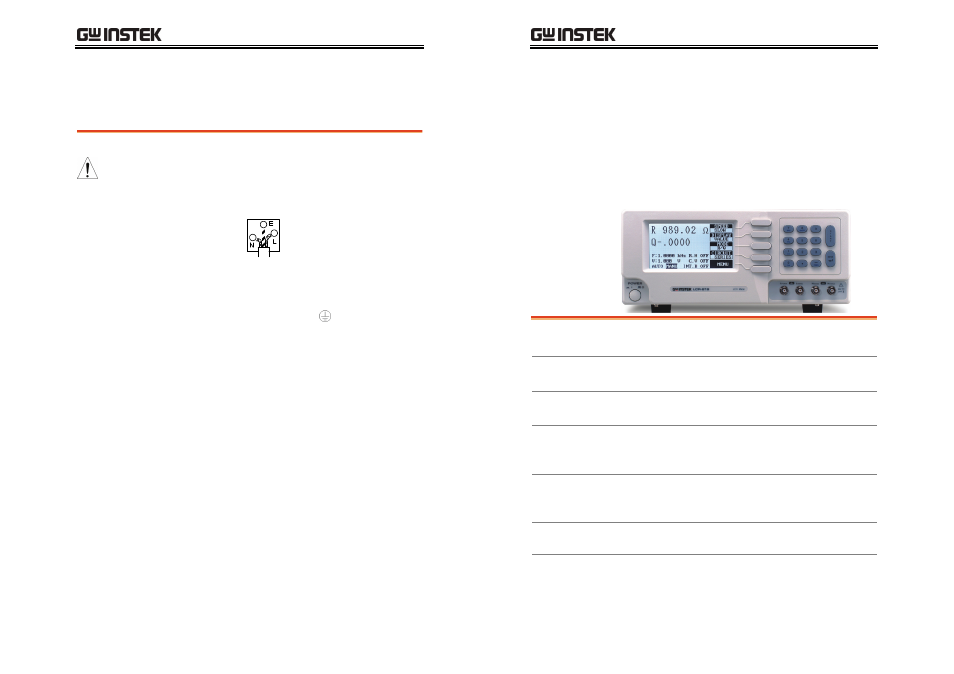
ETTING STARTED
This chapter describes the instrument’s main
features, front & rear panels, power up sequence,
fixture connections and calibration.
Main Features
Main Features .............................................................. 11
Model comparison ...................................................... 12
Measurement type
Measurement item ...................................................... 12
Measurement combination ......................................... 12
Panel overview
Front Panel Overview .................................................. 13
Rear Panel Overview .................................................... 16
Setup
Power Up ..................................................................... 18
Tilt stand ...................................................................... 18
Power up ...................................................................... 18
Fixture connection
Fixture Connection ...................................................... 20
Fixture structure .......................................................... 20
Fixture connection ....................................................... 21
Bias voltage
connection
External voltage bias connection ................................ 22
Zeroing
Zeroing ......................................................................... 24
Zeroing calibration ...................................................... 24