GW Instek LCR-800 Series User Manual
Page 11
GETTING
STARTED
21
Fixture connection
Panel operation
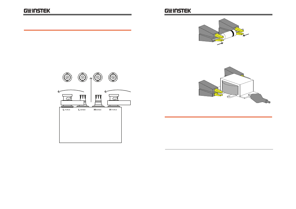
1. Discharge the test component before connecting
the fixture set.
2. Connect the Kelvin clip test lead into the front
terminals. Line the lead fixture up to the front
terminals and slide in. Turn the BNC handle
counter clockwise to unlock the fixture. Turn
the handles clockwise to lock the fixture.
TEST LEADS
3. Connect the fixture to the test component. If the
component has polarity, connect the H side to
the positive lead and the L side to the negative
lead. Make sure the distance between the lead
base and fixture clip is short enough.
LCR-800
User
Manual
22
H side
L side
4. If the test component has an outer case
unconnected to either of the leads, connect to
the ground terminal for noise level reduction.
External voltage bias connection
Background
An external voltage bias of 0-30 volts with a
maximum of 200mA can be applied to the external
voltage bias terminals on the rear panel. The
external bias voltage must be floating and not
connected to ground. For details for setting the
external bias voltage see page 34.
1. Connect the voltage bias terminals to a bias
voltage. Leave ground floating.