A3.2.3 network cable connection, A3.2.3.1 optical network cable connection, A3.2.3 – Yokogawa YFGW710 User Manual
Page 30: A3-10, Important
A3-10
IM 01W01F01-01EN
l
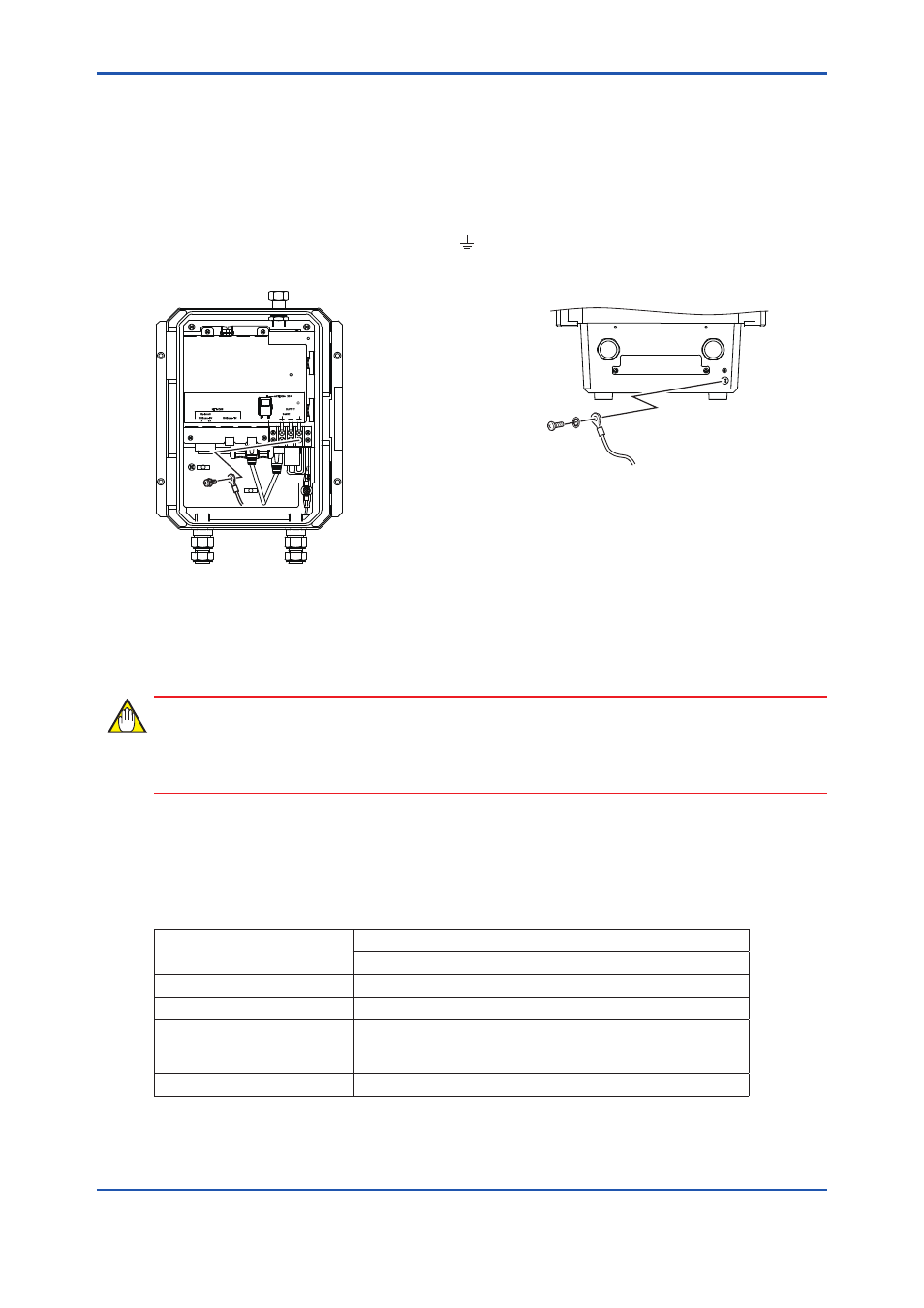
Connection of Cable
The grounding terminals are located on the inside and outside of the terminal area.
Connect the cable to grounding terminal in accordance with wiring procedure 1) or 2).
1) Internal grounding terminal
If the power cable is a shielded cable, the shield
should be grounded at the terminal marked
as below.
2) External grounding terminal
M4 screw
(Bottom of the enclosure)
FA0308.ai
Fig. A 3-8 Wiring Procedure for Grounding Terminals
A3.2.3 Network Cable Connection
This section describes the connection of the optical and metal network cables.
IMPORTANT
According to the requirement of communication specification, select the optical Ethernet or the
metal Ethernet to communicate with the higher layer application.
A3.2.3.1 Optical Network Cable Connection
l
Applicable Cable
Table A 3-2 Specification of Optical Network Cable
Item
Specification
Optical Fiber Cable
Standard
100Base-FX
*1
Connector
SC Connector (1-pole x 2)
*2
Applicable Cable
Multi Mode Fiber (Central wavelength: 1300 nm)
50/125 um or 62.5/125 um
Inner tension must be nonmetals, such as FRP.
Transmission Range
2 km (Max.)
*1: 100Base-TX (Refer table A3-3) and 100Base-FX must be used exclusively.
*2: A double ferrule SC connector cannot be used. Be sure to use a single ferrule type.