A3.2.2 ground cable connection, A3.2.2, A3-9 – Yokogawa YFGW710 User Manual
Page 29: Important
A3-9
IM 01W01F01-01EN
l
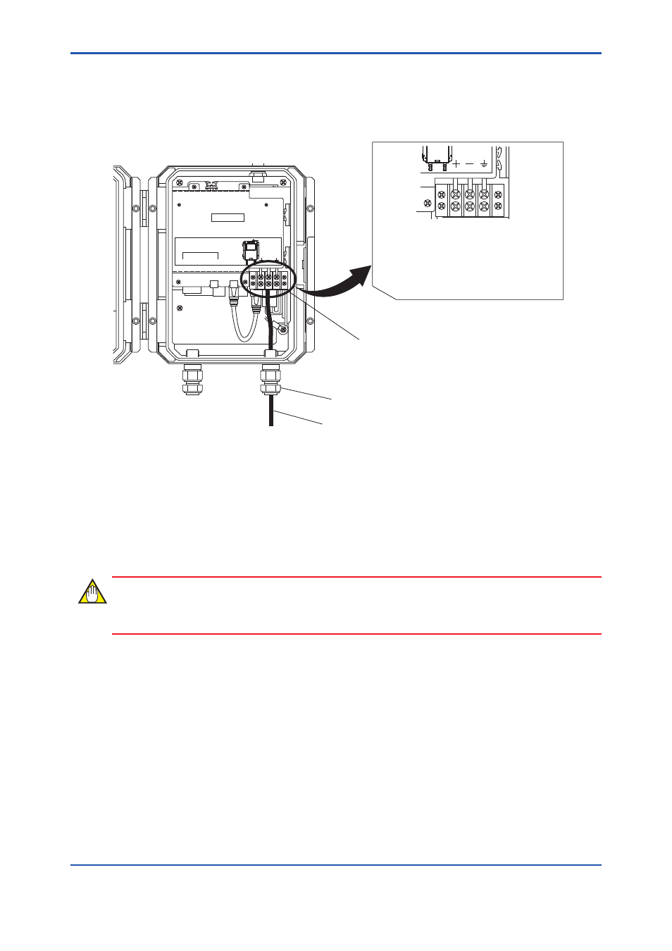
Connection Procedure of Power Cable
1. Pull the power cable into the housing of YFGW710 through the power cable ground.
2. Connect + lead wire to + terminal and – lead wire to – terminal.
3. Tighten the terminal screw with a torque of 1.2 to 1.4 N∙m.
NETWORK
SUPPLY
ANTENNA 50Ω
(Optional)
100Base-FX
100Base-FX
TX
RX
SUPPLY
Cable gland for power supply cable
Power supply cable
Power supply terminal
FA0307.ai
Connect the + and – wires to the + and –
terminals, respectively.
If the power cable is a shielded cable, the
shield should be grounded at terminal and
the grounding of the whole cable should be
restricted to this point only.
Fig. A 3-7 Power Supply Cable Connection
A3.2.2 Ground Cable Connection
This section describes ground wiring.
Class D grounding (the third class grounding) with the grounding resistance of 100 Ω or less is
necessary. To connect the grounding cable to YFGW710 directly, use the grounding terminal on
the right bottom of the main body. Do not share the ground wiring with other devices.
IMPORTANT
The explosion proof compliant device always needs the grounding.
l
Applicable Cable (Insulated wire for industrial equipment)
Examples:
• 600 V polyvinyl chloride insulated wires (IV): JIS C3307
• Polyvinyl chloride insulated wires for electrical apparatus (KIV): JIS C3316
• 600 V grade heat-resistant polyvinyl chloride insulated wires (HIV): JIS C3317
• Heatproof vinyl insulated wires VW-1 (UL1015/UL1007)
Wire Size
• Core: AWG14 to 13 (2 to 2.6 mm
2
)
Terminal Treatment
• Ring terminal for M4: With insulation covers