6 wiring procedure, Wiring procedure -6, Warning – Yokogawa ADMAG AXR User Manual
Page 30: Important
<4. WIRING>
4-6
IM 01E30D01-01EN
The description of the terminal symbols is shown in
Table 4.5.1.
Table 4.5.1 Terminal Symbols
No. Terminal Symbols
Description
➀
Functional grounding
➁
➂
+
–
SUPPLY
Power supply and current output
➃
➄
+
–
DO
Digital output (One output can be selected
from pulse, alarm or status outputs.)
(3) Terminal Configuration (TIIS Explosion
Proof Type)
When the cover is removed, the connection
terminal will be visible.
F0413.ai
SUPPLY
DO
➀
➂
➃
➄
➁
➅
Figure 4.5.3 Terminal Configuration
The description of the terminal symbols is shown in
Table 4.5.2.
Table 4.5.2 Terminal Symbols
No. Terminal Symbols
Description
➀
Functional grounding
➁
Class A grounding
➂
➃
+
–
SUPPLY
Power supply and current output
➄
➅
+
–
DO
Digital output (One output can be selected
from pulse, alarm or status outputs.)
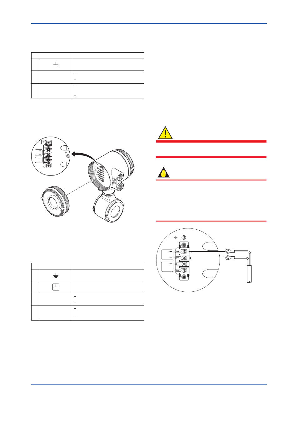
4.6 Wiring Procedure
(1) Power supply and Current output
This instrument uses the same two wires for both,
the signal and power supply. A DC power supply is
required in a transmission loop.
The allowable power supply voltage is described
below.
• 14.7 to 42V DC for general-purpose use and
explosion proof type
• 14.7 to 32V DC for lighting Protector (optional
code A)
Wire the AXR according to Figure 4.6.1.
WARNING
Before wiring with external instruments, be sure
to turn off the external instruments.
IMPORTANT
This instrument normally outputs a current of 12
mA for several seconds just after turning on the
power.
Warm up this instrument for at least 30 minutes.
Perform flow measurement 30 minutes after
turning on the power.
F0414.ai
SUPPLY
DO
Power supply
cable
Figure 4.6.1 Electric Cable Wiring (General -
purpose Use/Explosion Proof Type
except TIIS)