Model and suffix code, Model and suffix code -9, Nmodel and suffix code – Yokogawa ADMAG AXR User Manual
Page 161: Wafer type
12-9
IM 01E30D01-01EN
<12. OUTLINE>
n
MODEL AND SUFFIX CODE
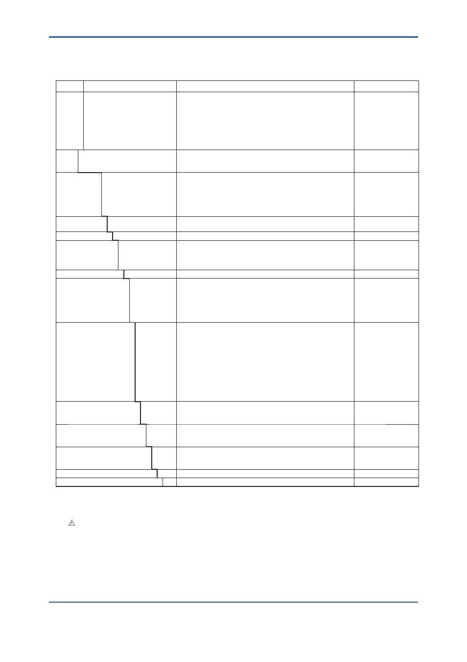
● Wafer Type
Model
Suffix Code
Description
Applicable Model
AXR025
AXR040
AXR050
AXR065
AXR080
AXR100
AXR150
AXR200
-------------------------------------------------
-------------------------------------------------
-------------------------------------------------
-------------------------------------------------
-------------------------------------------------
-------------------------------------------------
-------------------------------------------------
-------------------------------------------------
Size 25 mm (1 in.)
Size 40 mm (1.5 in.)
Size 50 mm (2 in.)
Size 65 mm (2.5 in.)
Size 80 mm (3 in.)
Size 100 mm (4 in.)
Size 150 mm (6 in.)
Size 200 mm (8 in.)
Two-wire Magnetic Flowmeter Integral Flowmeter
Two-wire Magnetic Flowmeter Integral Flowmeter
Two-wire Magnetic Flowmeter Integral Flowmeter
Two-wire Magnetic Flowmeter Integral Flowmeter
Two-wire Magnetic Flowmeter Integral Flowmeter
Two-wire Magnetic Flowmeter Integral Flowmeter
Two-wire Magnetic Flowmeter Integral Flowmeter
Two-wire Magnetic Flowmeter Integral Flowmeter
Use
G -------------------------------------------------
C -------------------------------------------------
General-Purpose Use
Explosion proof Type (*1)
Size 25 mm (1.0 in.) to
100 mm (4.0 in.)
Output Signal
and
Communication
-D -----------------------------------
-E -----------------------------------
-J -----------------------------------
Integral Flowmeter with 4 to 20 mA DC Output and digital
communication (BRAIN protocol)
Integral Flowmeter with 4 to 20 mA DC Output and digital
communication (HART protocol) (*12)
Integral Flowmeter with 4 to 20 mA DC Output with digital
communication (HART5/HART7 protocol) (*13)
Power Supply
1 --------------------------------- Integral Flowmeter Operating voltage range 14.7 to 35 V DC
Two-wire system
Lining (*2)
A ------------------------------ Fluorocarbon PFA
Electrode Material (*2)
L ---------------------------
P ---------------------------
H ---------------------------
T ---------------------------
JIS SUS316L (AISI 316L SS/EN 1.4404 Equivalent)
Platinum-iridium
Hastelloy C276 Equivalent
Tantalum
Electrode Structure
1 ------------------------ Non-replaceable
Grounding Ring and
Grounding Electrode
Material (*2)
N --------------------
S --------------------
L --------------------
P --------------------
H --------------------
T --------------------
None (*3)
JIS SUS316 (AISI 316 SS/EN 1.4401 Equivalent)
JIS SUS316L (AISI 316L SS/EN 1.4404 Equivalent)
Platinum-iridium
Hastelloy C276 Equivalent
Tantalum
Process Connection
(*4) (*5)
-AA1 -------------
-AA2 -------------
-AD1 -------------
-AD2 -------------
-AD4 -------------
-AJ1 -------------
-AJ2 -------------
-AG1 -------------
ANSI Class 150
Wafer
ANSI Class 300
Wafer
DIN PN 10
Wafer (*6)
DIN PN 16
Wafer (*6)
DIN PN 40
Wafer (*6)
JIS 10K
Wafer
JIS 20K
Wafer
JIS F12 (JIS75M)
Wafer
Size 200 mm (8.0 in)
Size 65 mm (2.5 in.) to
200 mm (8.0 in.)
Size 25 mm (1.0 in.) to
50 mm (2.0 in.)
Size 80 mm (3.0 in.) to
200 mm (8.0 in.)
Lay Length
1 ---------------
2 ---------------
Lay length code 1 (*7)
Lay length code 2 (*8)
Size 80 mm (3.0 in.) to
200 mm (8.0 in.)
Electrical Connection (*9)
-0 -----------
-2 -----------
-4 -----------
JIS G1/2 female
ANSI 1/2 NPT female
ISO M20 × 1.5 female
Indicator (*10)(*11)
1 ---------
2 ---------
N --------
Integral Flowmeter with indicator (Horizontal)
Integral Flowmeter with indicator (Vertical)
Integral Flowmeter without indicator
Calibration
B ----- Always B
Options
/
Optional code (See the Table of Optional Specifications)
*1: For explosion proof types, specify types of explosion proof certification using the optional codes.
For the TIIS flameproof type, select optional code G11. Available only for JIS G1/2 female electrical connections.
Available only for wiring of using a flameproof packing adapter approved by Yokogawa.
The flameproof metal conduit wiring for TIIS flameproof type is not permitted.
*2: Users must consider the characteristics of selected wetted parts material and influence of process fluids.
The use of inappropriate materials can result in the leakage of corrosive process fluids and cause injury to personnel and/or damage
to plant facilities. It is also possible that the instrument itself can be damaged and that fragments from the instrument can contami-
nate the user’s process fluids.
Be very careful with highly corrosive process fluids such as hydrochloric acid, sulfuric acid, hydrogen sulfide, sodium hypochlorite,
and high-temperature steam (150°C [302°F] or above). Contact Yokogawa for detailed information of the wetted parts material.
*3: Available only for metal piping.
*4: Mating dimensions are based on standards as follow:
ANSI: ASME B 16.5, DIN: DIN 2501, JIS: JIS B 2220 and JIS G 3443-2