2 trim analog output, Trim analog output -5, Caution – Yokogawa ADMAG AXR User Manual
Page 124
<9. OPERATION VIA HART CONFIGURATION TOOL (HART 7)>
9-5
IM 01E30D01-01EN
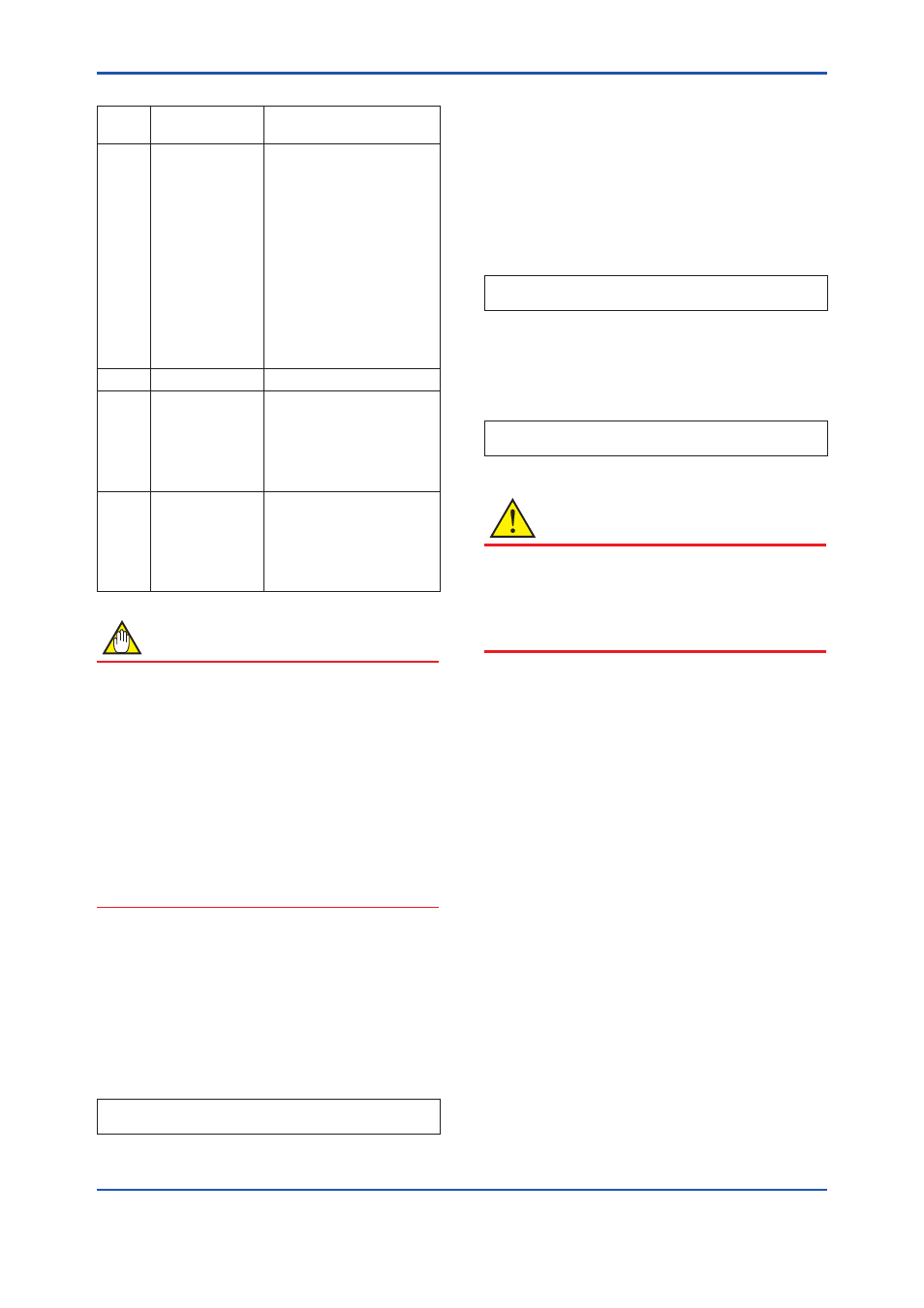
• Procedure of device variable simulation
Step 1 Call up the
parameter
[Root Menu] → Diagnosis/
Service → Test → Simulate
2
Selection of
Device Variable
Select one parameter from
the list below
Off
PV (Instantanous flow
rate)
SV (Forward totalization
value)
TV (Reverse totalization
value)
QV (Differential totalization
value)
% Range (% in output)
Loop Current (current
output)
3
Setting of Value
Input the simulate value
4
Setting of Data
quality
Select one parameter from
the list below
Bad
Poor accuracy
Manual / Fixed
Good
5
Setting of Limit
status
Select one parameter from
the list below
Not limited
Low limited
High limited
Constant
NOTE
• The total is accumulated from the
instantanous flow rate. Therefore, the total
depends on the instantanous flow rate.
• The total simulation is only applied for LCD
display and communication output and does
not affect the totalization value.
• The simulations for flow rate are reflected
to the output. Accordingly, the loop current,
LCD display, and communication output are
directly corresponded to the simulate value.
The alarm output is also available according
to the simulate value.
(3) Squawk
This feature can be used to identify the
communicating device by remotely causing LCD
to display the particular pattern as shown in the
Figure.
“SQUAWK” continues for approximately 60
seconds, then is released automatically.
• Procedure to call up the
Squawk display
[Root Menu] → Diagnosis/Service → Test → Squawk
→ Squawk
9.8.2 Trim Analog Output
This function is used to adjust the analog output at 4
mA and 20 mA with the D/A trim.
(1) D/A trim
Connect a calibration digital ammeter, and then
enter the read value of the ammeter for each
output of AXR.
• Procedure to call up the
D/A trim display
[Root Menu] Diagnosis/Service → Adjustment → D/A
trim
(2) Clear D/A trim
When output is reset to the original value, clear
the D/A trim.
• Procedure to call up the
Clear D/A trim display
[Root Menu] Diagnosis/Service → Adjustment → Clear
D/A trim
CAUTION
The output adjustment function can match the
4mA and 20mA output to the reference meter
such as a voltmeter. In the output adjustment, it
is necessary to use the calibrated voltmeter and
resistance.