2 internal peripheral interface connectors – IEI Integration eKINO-945GSE v1.01 User Manual
Page 48
eKINO-945GSE Motherboard
Page 32
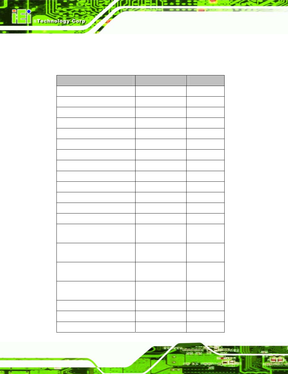
4.1.2 Internal Peripheral Interface Connectors
Table 4-1 shows a list of the peripheral interface connectors on the eKINO-945GSE.
Detailed descriptions of these connectors can be found below.
Connector
Type
Label
Battery connector
2-pin box header
BT1
CompactFlash® slot
CompactFlash® slot
J2
Digital I/O connector
10-pin header
DIO1
Fan connector
3-pin wafer
J1
Front panel connector
14-pin header
F_PANEL1
IDE connector
44-pin box header
IDE1
Infrared connector
5-pin header
IR1
Keyboard/Mouse connector
6-pin box header
MS/KB1
LCD backlight inverter connector
5-pin box header
INVERTER1
LED connector
6-pin connector
J3
LVDS connector
30-pin crimp
LVDS1
MCU LAN connector
8-pin box header
J10
PCIe Mini slot
PCIe Mini connector
MINI_PCIE1
Power connectors
Power connectors
PWR1
CN2
SATA drive connectors
SATA port
SATA1
SATA2
SATA power connectors
4-pin box header
PW1
PW2
Serial port connectors (RS-232)
10-pin header
COM3
COM4
Serial port connector (RS-422/485) 6-pin
header
JP2
SO-DIMM socket
SO-DIMM socket
DIMM1
SPDIF connector
5-pin header
SPDIF1