2 compactflash® slot, 3 low pin count (lpc) interface, 4 pci bus – IEI Integration eKINO-945GSE v1.01 User Manual
Page 33: 1 pci expansion card slot, Table 2-1: supported hdd specifications
eKINO-945GSE Motherboard
Page 17
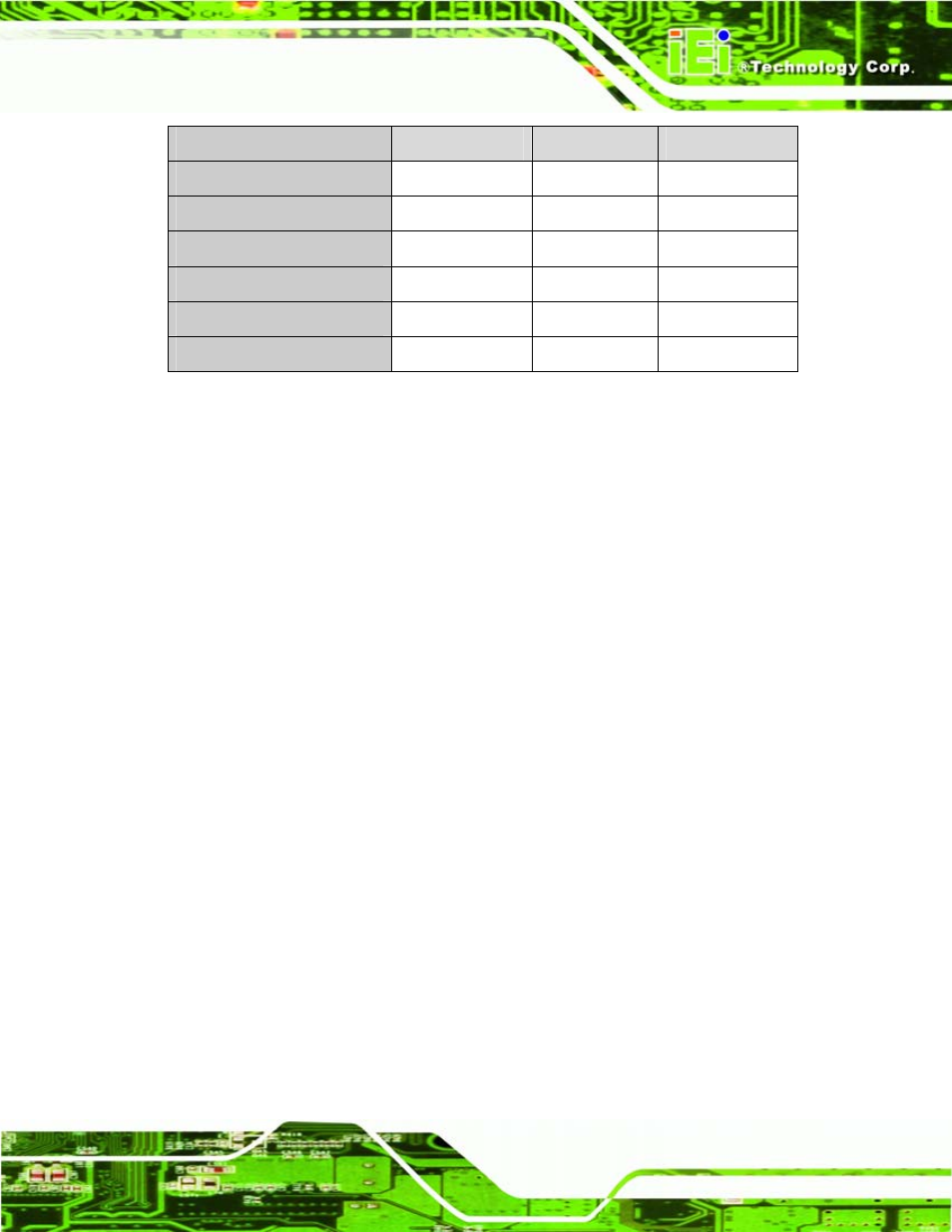
Specification
Ultra ATA/100
Ultra ATA/66
Ultra ATA/33
IDE devices
2 2
2
PIO Mode
0 – 4
0 – 4
0 – 4
PIO Max Transfer Rate
16.6 MB/s
16.6 MB/s
16.6 MB/s
DMA/UDMA designation
UDMA 5
UDMA 4
UDMA 2
DMA/UDMA Max Transfer
100 MB/s
66 MB/s
33 MB/s
Controller Interface
5 V
5 V
5 V
Table 2-1: Supported HDD Specifications
2.5.2.2 CompactFlash® Slot
The CompactFlash® slot on the eKINO-945GSE is interfaced through the IDE interface on
the Intel® ICH7M Southbridge. The CompactFlash® slot is shown in Figure 2-5.
2.5.3 Low Pin Count (LPC) Interface
The Intel® ICH7M LPC interface complies with the LPC 1.1 specifications. The LPC bus
from the Intel® ICH7M is connected to the following components:
BIOS
chipset
Super I/O chipset
2.5.4 PCI Bus
The PCI interface on the Intel® ICH7M is compliant with the PCI Revision 2.3
implementation. Some of the features of the PCI interface are listed below.
PCI Revision 2.3 compliant
33
MHz
5 V tolerant PCI signals (except PME#)
Integrated PCI arbiter supports up to seven PCI bus masters
2.5.4.1 PCI Expansion Card Slot
The PCI interface is connected directly to the PCI expansion card slot on the
eKINO-945GSE. The location of the PCI expansion card slot is shown in Figure 2-5.