Teledyne LeCroy USB Chief - Users Manual User Manual
Page 23
15
Chief User’s Manual
CATC
Version 1.7
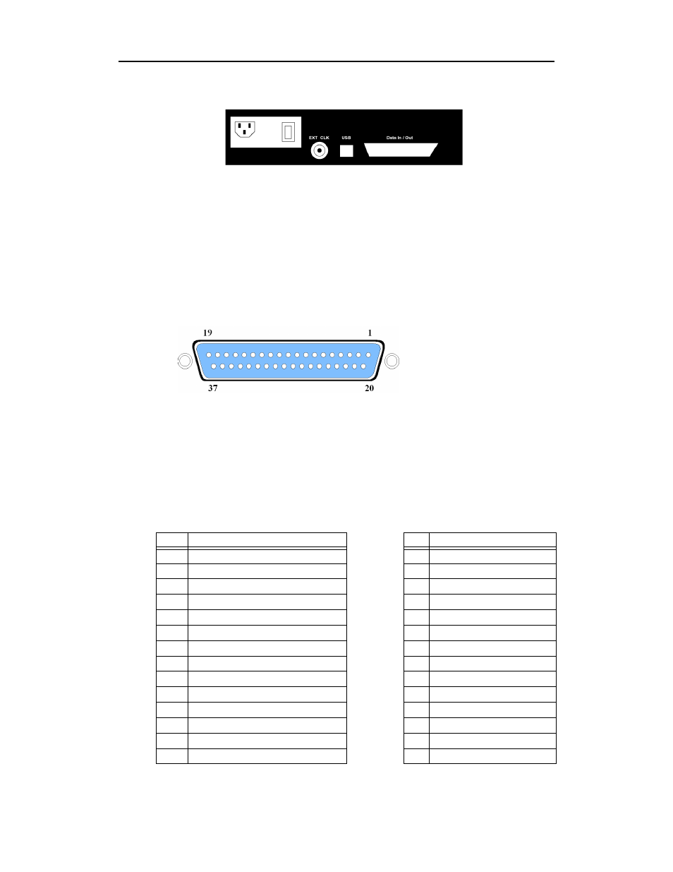
Figure 2: Rear Panel
•
Wide range AC connector module
— Power socket
— Enclosed fuse
— Power on/off switch
•
External Clock (EXT CLK) input for future enhancement
•
USB type “B” host computer connector
•
Data In/Out DB-37 (37-pin) external interface connector
Figure 3: Data In/Out Connector
Use the 37-pin Data In/Out connector located on the rear of the USB Chief
Analyzer box to connect the External Interface Breakout Board.
Table 1 lists the pin-out and signal descriptions for the Data In/Out connector.
Signal inputs (IN x) function under the control of the USB Chief program and may
be set as active-low or active-high in Recording Options. Signal inputs 0 through
3 can be recorded optionally along with USB traffic and displayed in a CATC
Trace. Signal outputs (OUT x) function under the control of the USB Chief
program and are used to link any events to an external signal.
Table 1: Data In/Out Connector – Pin-Out
Pin
Signal Description
Pin
Signal Description
1
5V, 500mA DC source
20
Ground
2
TRIGGER OUT (active low)
21
Ground
3
Not connected
22
Ground
4
IN 0 – Signal input
23
Ground
5
IN 1 – Signal input
24
Ground
6
IN 2 – Signal input
25
Ground
7
IN 3 – Signal input
26
Ground
8
IN 4 – Signal input
27
Ground
9
TRIGGER IN
28
Ground
10
CURRENT MEASURE +
29
Ground
11
CURRENT MEASURE -
30
Ground
12
OUT 0 – Signal output
31
Ground
13
OUT 1 – Signal output
32
Ground
14
OUT 2 – Signal output
33
Ground