System components/packing list, Stand-alone unit – Teledyne LeCroy USB Chief - Users Manual User Manual
Page 22
14
Chief User’s Manual
CATC
Version 1.7
•
Real-time traffic capture filtering
†
•
Automatic detection and capture of full- and low-speed traffic
†
†
new or enhanced feature not available in the Detective or Inspector Analyzer
System Components/Packing List
•
One stand-alone USB Chief Analyzer unit with AC power cord
•
One External Interface Breakout Board with a 37-pin ribbon cable
•
Three USB cables: two 3-foot (1-meter) cables and one 6-foot (2-meter) cable
•
USB Chief software program installation diskette(s)
•
Product documentation including on-line help
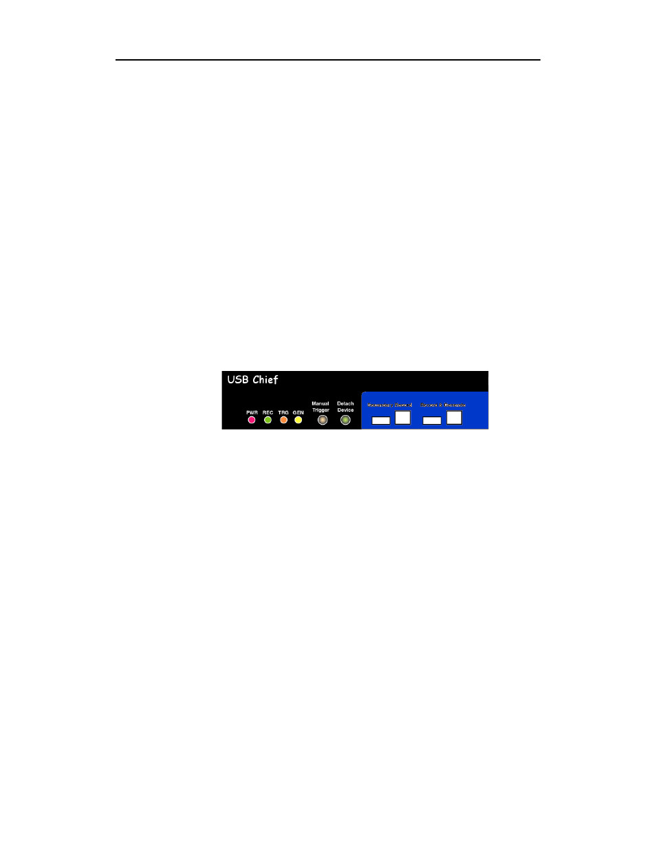
Stand-Alone Unit
The USB Chief Analyzer has several user-accessible controls on its front and rear
panels.
Figure 1: Front Panel
•
Red PWR (power) indicator LED (lights when the unit power is switched on)
•
Green REC (recording) LED (lights when the unit is recording)
•
Yellow TRG (triggered) LED (lights when the unit triggers an event)
— Also lights during power-on testing and blinks when the hardware is faulty
•
Yellow GEN (generate) LED (lights when the unit is generating traffic)
•
Manual Trigger push-button (allows a manual Trace capture)
— After beginning a recording session, press the Manual Trigger switch to
force a Trigger condition. The session completes when a specified
post-Trigger amount of bus data is recorded or when you manually stop a
recording session.
•
Detach Device push-button (allows a momentary disconnection of the device
from the host on the primary port).
— This is especially useful when the traffic of interest occurs during device
enumeration. Use the Detach Device switch shortly after starting
recording to capture a Trace of the device’s enumeration.
•
Two USB ports, Record & Generate (Primary Port) and Secondary Record
(Secondary Port), each with a type "A" and a type "B" connector
— (Record & Generate) records and generates traffic
— (Secondary Record) records only