Agilent Technologies L4400 User Manual
Page 20
8
L4400 User’s Guide
1
Introduction to the L4400 Series LXI Instruments
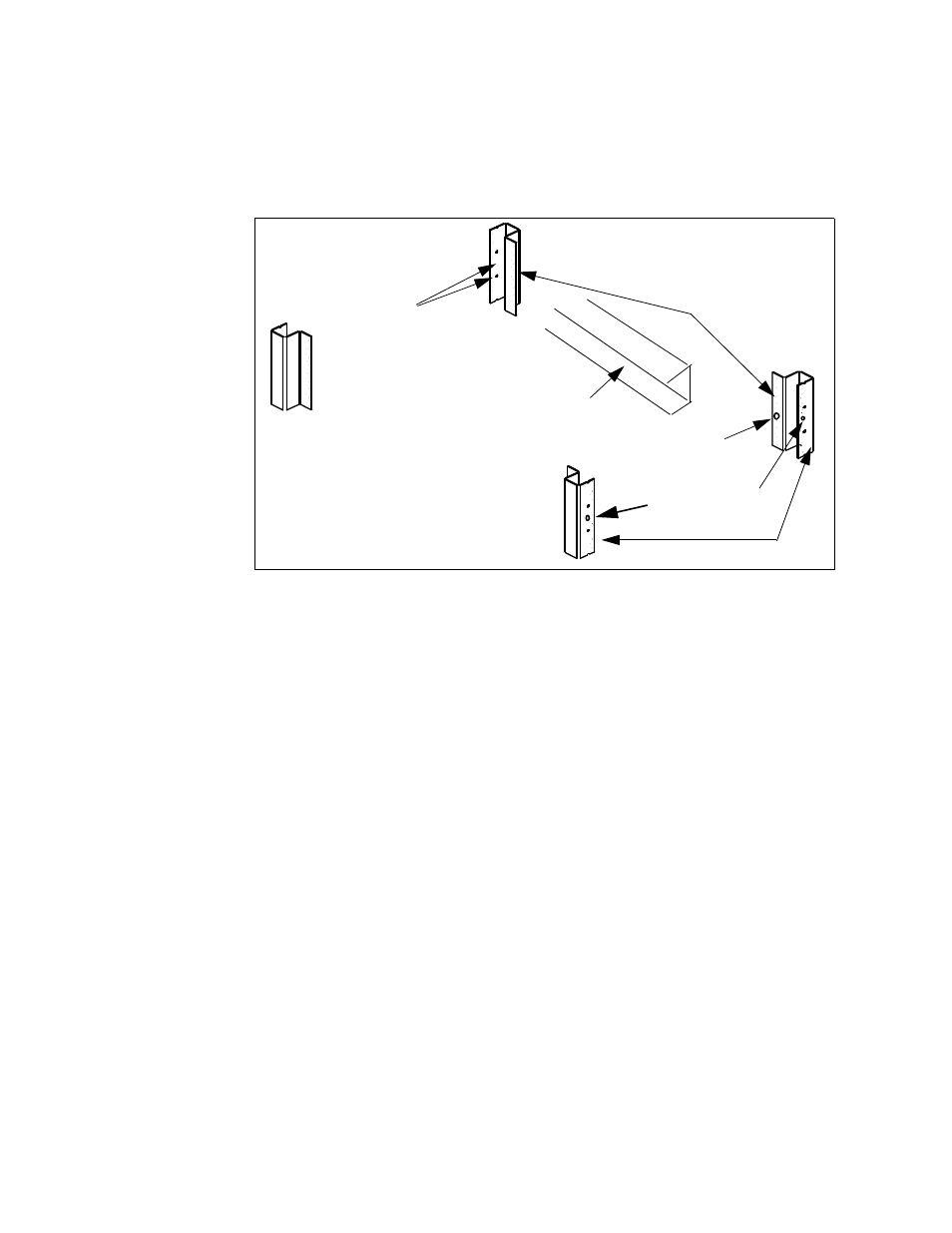
If center- facing columns with holes are present on the frame, insert a
clip- on nut on the hole perpendicular to the center hole on the front
facing column. See Figure 1- 3.
(center of rack)
front-facing columns
center-facing colums
back of rack
insert clip nuts
between rack unit
indicators
insert clip nut
if column present
insert clip nuts
on first and third
holes between indicators
rail “channel
Figure 1-3. Rack Column and Shelf Rail Orientation.
2. With the rail “channel” facing the center of the rack, connect the rail
to the front facing column using a 10- 32 flathead screw (item 4) and the
center clip- on nut on the front- facing column. Repeat for the rail on the
opposite column. Ensure the rail channel faces the center of the rack.
If the rack has center- facing columns (Figure 1- 3), insert a 10- 32 pan
head screw through the rail opening and clip nut (perpendicular to the
front- facing column). Repeat for the rail on the opposite column.
3. On the rack’s rear- facing columns, insert clip- on nuts on the first and
third holes between the EIA unit indicators that are at the same vertical
position as the indicators on the front- facing columns.
4. Attach the rear brackets to the rail ends using two 10- 32 pan head
screws (item 3) and two 10- 32 nuts with lockwashers (item 6) per rail.
Adjust the bracket along the rail until the bracket end aligns with
(covers) the rack’s rear- facing columns. Tighten the 10- 32 pan head
screws to firmly connect the bracket to the rail and maintain the rail
length.
Connect the rail brackets to the rear- facing columns using two 10- 32 pan
head screws per column.