Fluid Components International GF03 User Manual
Page 6
FLUID COMPONENTS INTERNATIONAL LLC http://www.fluidcomponents.com
Model GF03 Flow Meter
2
Doc. No. 06EN003352 Rev. B
INSTRUMENT
Flow Range:
Insertion Flow Element: 0.5 to 275 SFPS [0.20 to 84 NMPS]
— Air at standard conditions; 70°F [21.1°C] and 14.7 psia [1.01325 bar (a)].
Media: All gases that are compatible with the flow element material.
Accuracy:
Flow: ±2% to 5% of reading above 1 SFPS in open stack environments.
Temperature: ±2°F (display only, flow rate must be greater than 5 AFPS)
Repeatability:
Flow: ±0.5% reading
Temperature: ±1°F (flow rate must be greater than 5 AFPS)
Turndown Ratio:
Standard: Factory set and field adjustable from 2:1 to 600:1 within calibrated flow range.
Temperature Compensation:
Standard: ±30°F [±-1°C] Optional: ±100°F [±38°C]
Agency Approvals (Pending):
FM, CSA, CE MARK, (EMC Directive 89/336/EEC), ATEX, CCE, CRN.
Calibration: Performed on NIST traceable equipment.
FLOW ELEMENTS
Material of Construction: All-welded 316L stainless steel. Elements with pressure
transducer have braze and 300 series SST.
Operating Pressure: 0 to 250 psig [0 to 17 bar (g)]
Operating Temperature: Process temperature -40°F to 350°F [-40°C to 177°C];
Process Connection: 1” male NPT, Flange (ANSI), Packing Gland 1-1/4” NPT or Flanged.
Technical
Specifications
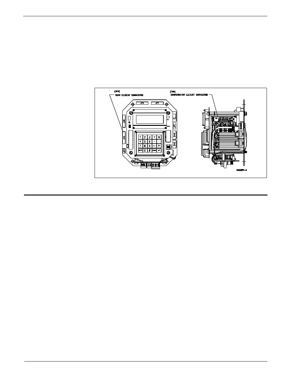
The other component of the flowmeter is the flow transmitter. The basic functions of the flow
transmitter are to provide power to the flow element, measure the Differential Temperature
(
∆
T) between the two RTDs as a function of resistance, amplify and linearize the Differential
Resistance (
∆
R) measurement of the flow element and provide a proportional output signal.
This output signal is calibrated to the flow rate as a function of standard velocity or volume.
To perform these functions, microprocessor-based electronic circuitry is employed to acquire
the analog voltage signals from the RTDs, digitize and interpret the information.
The microprocessor-based electronics provides maximum flexibility and ease of operations
with a menu-driven selection of control, monitoring, display and driver options.
Flow Transmitter
Figure 2 - Flow Transmitter